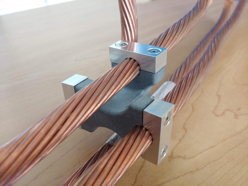
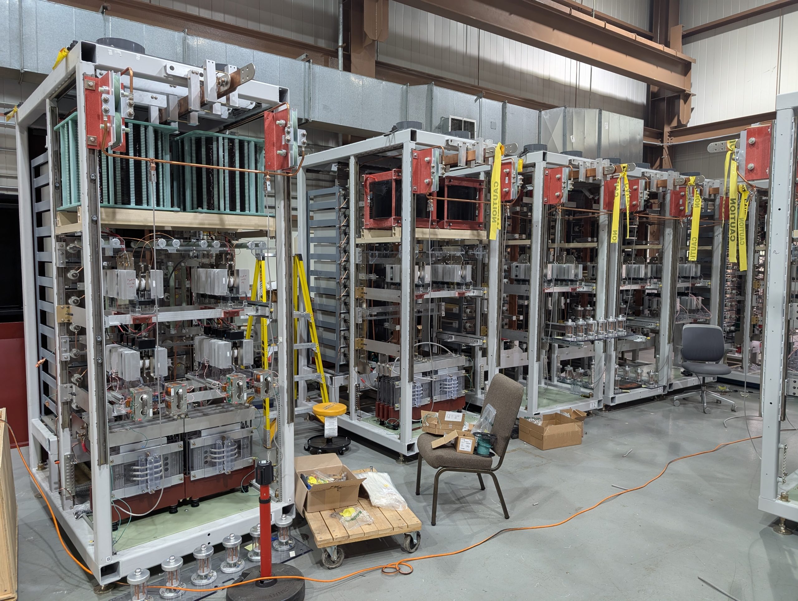
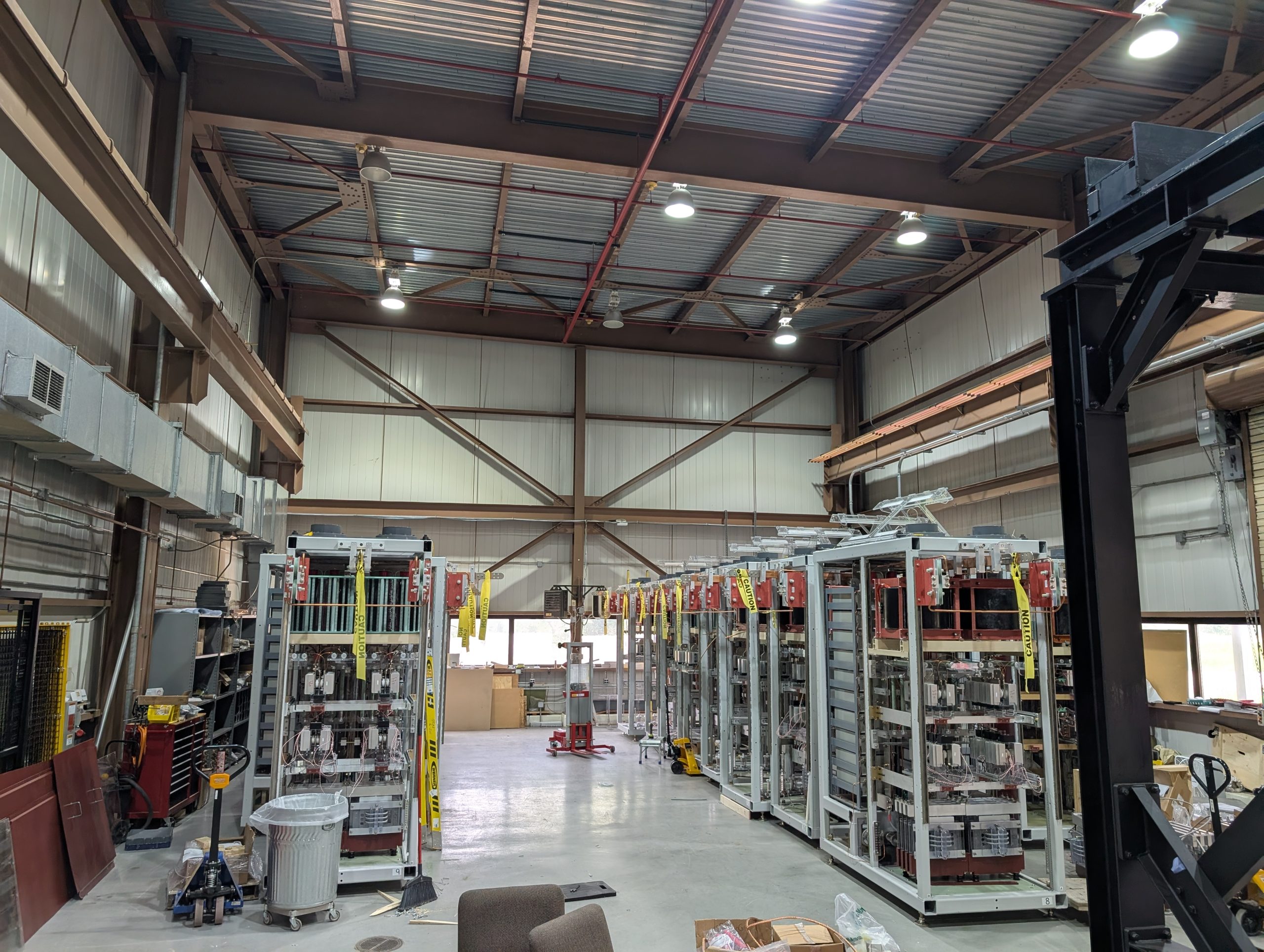
To power the neutrino focusing horns for the upcoming Long Baseline Neutrino Facility (LBNF), 300,000 amps of current will flow through nine alternating-polarity aluminum conductors held at 5,000V from the power supply to the three focusing horns. Most of the stripline resides in a radiation environment that quickly degrades coppers, high-strength steels, and most plastics. Despite the harsh environment and the massive magnetic forces generated with each electrical pulse, the stripline is expected to survive for 30 years and one-billion pulses! These requirements make designing what looks like a bunch of simple aluminum bars a surprisingly challenging venture.
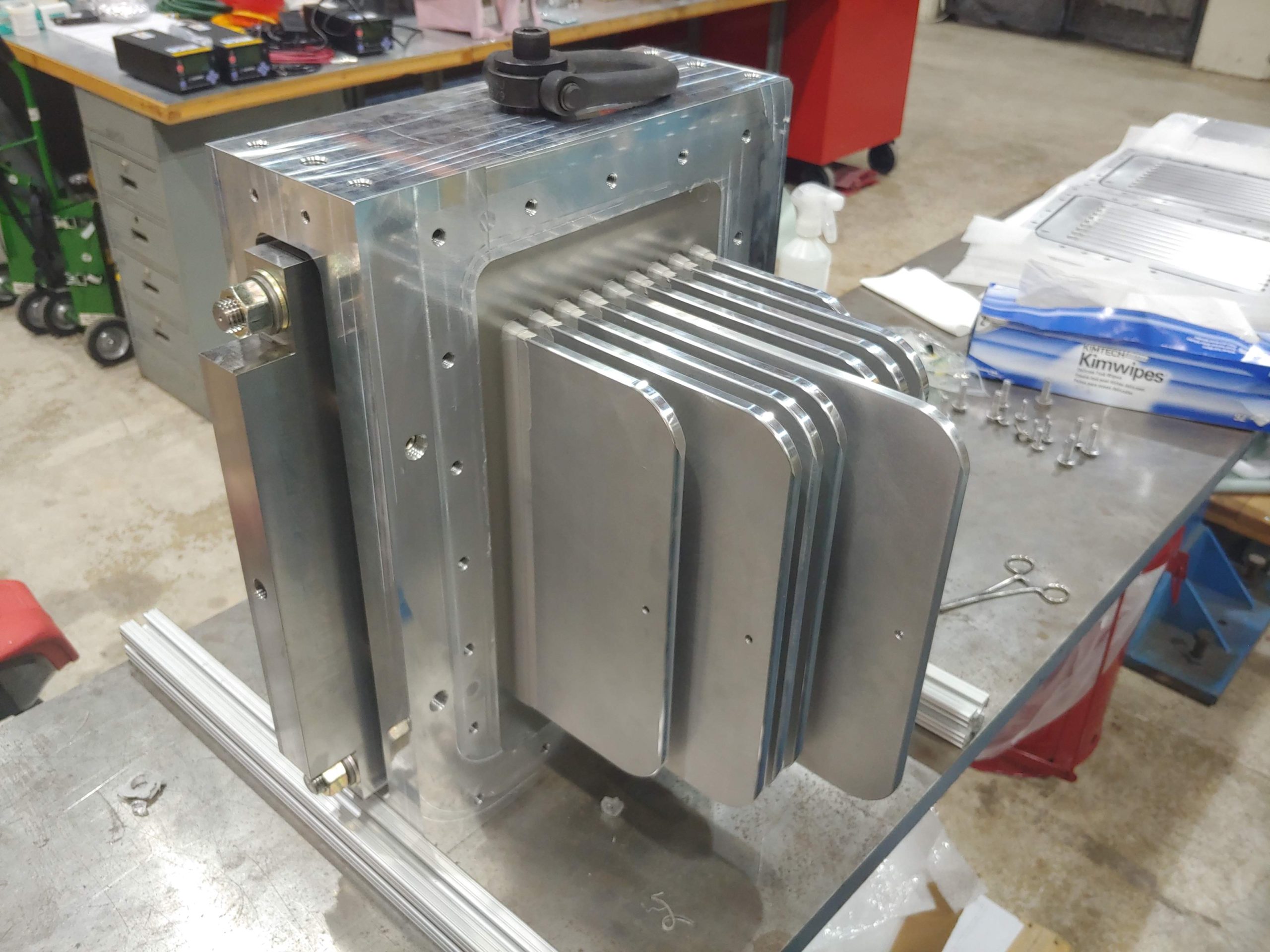
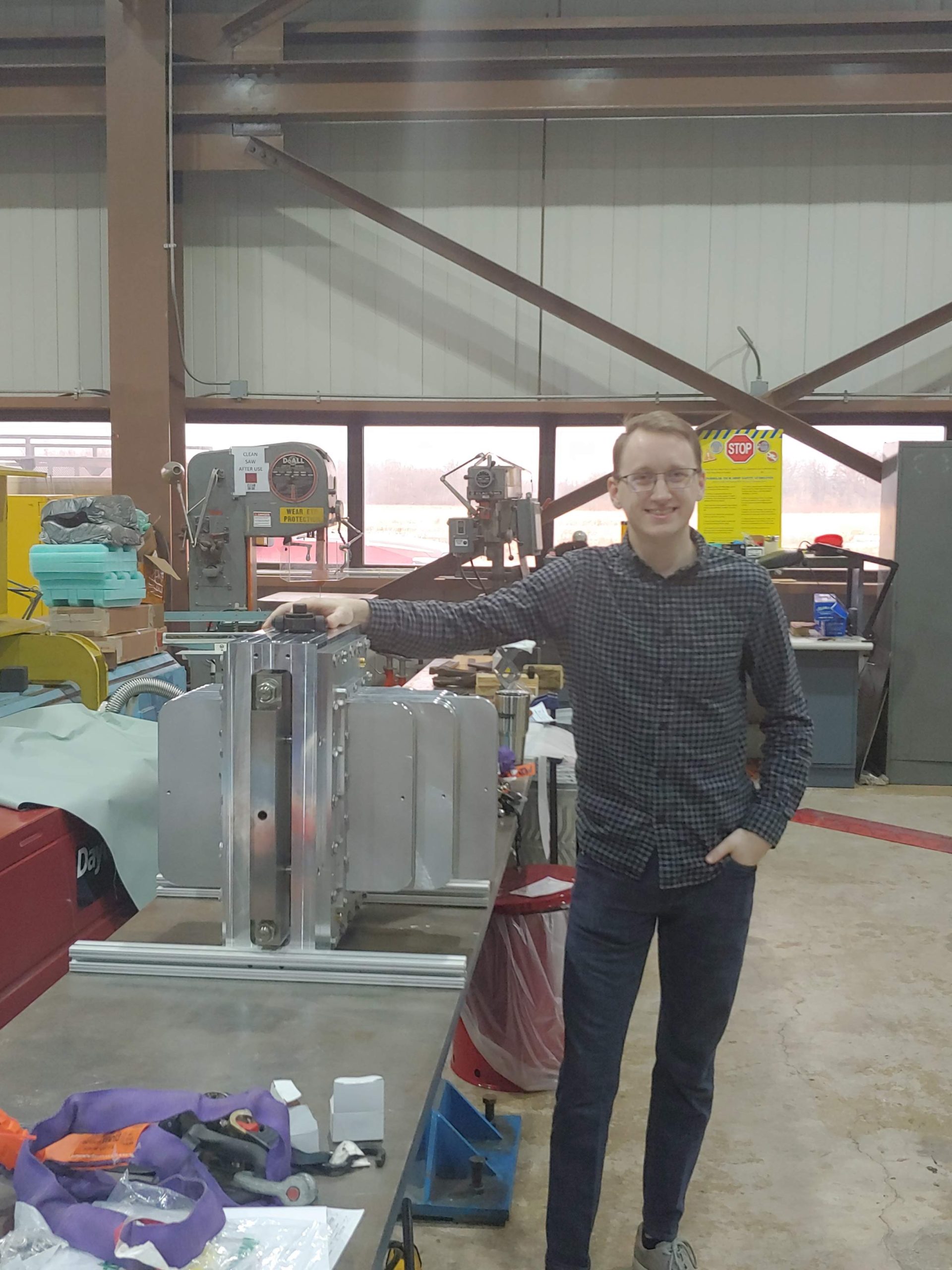
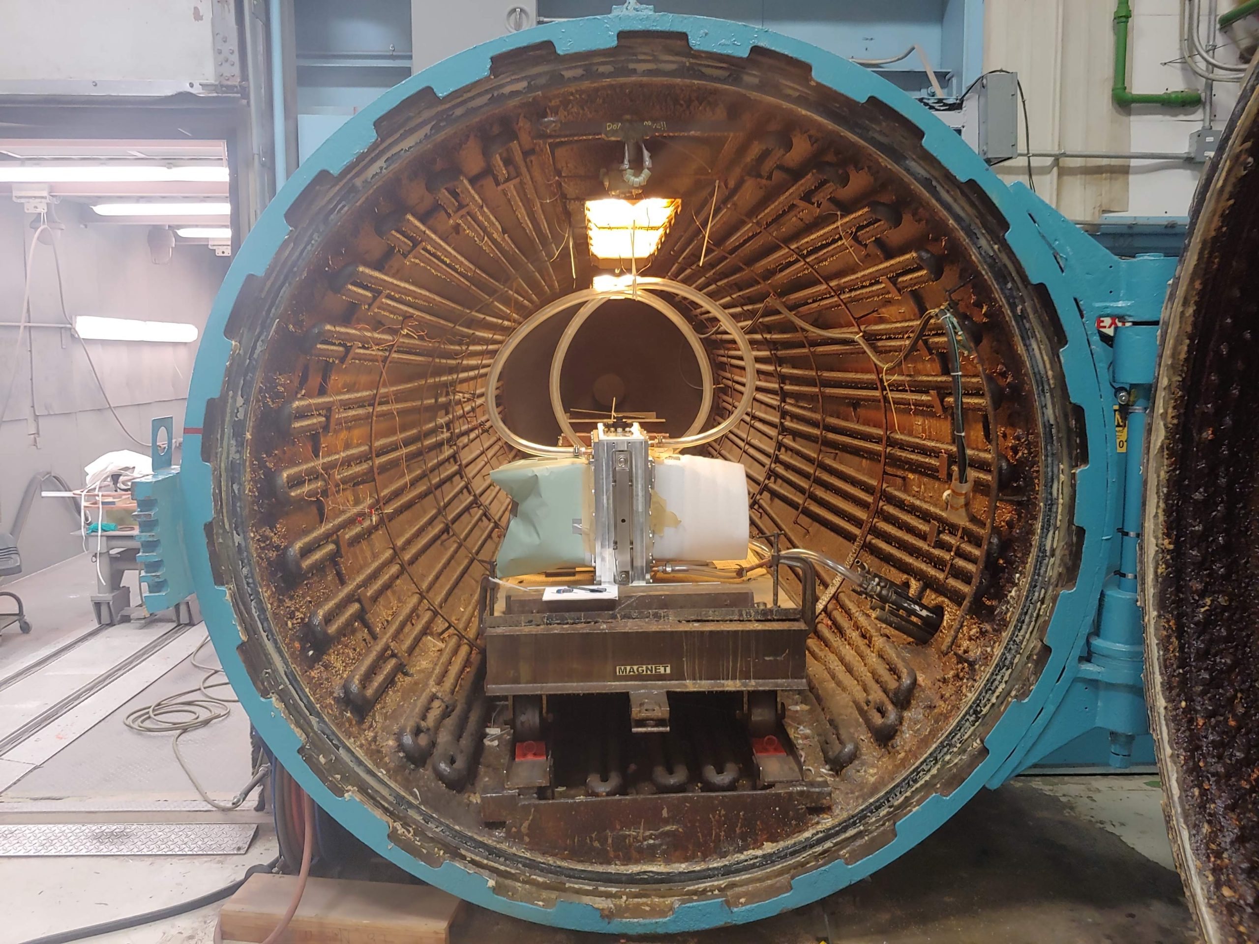
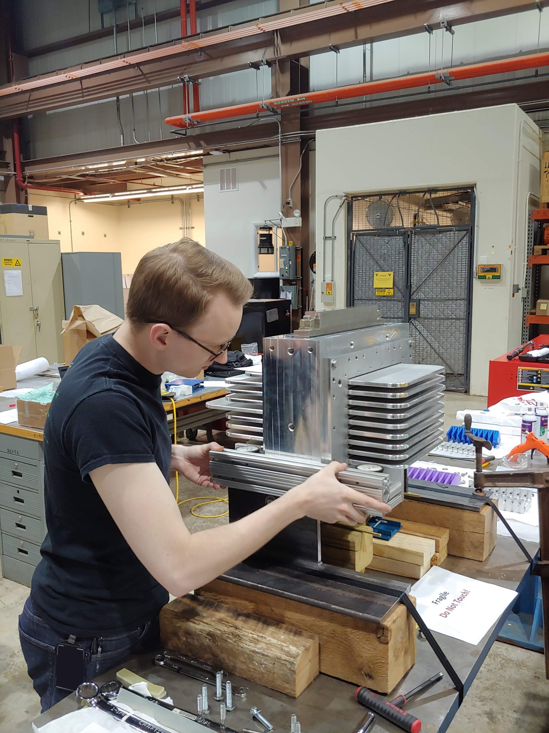
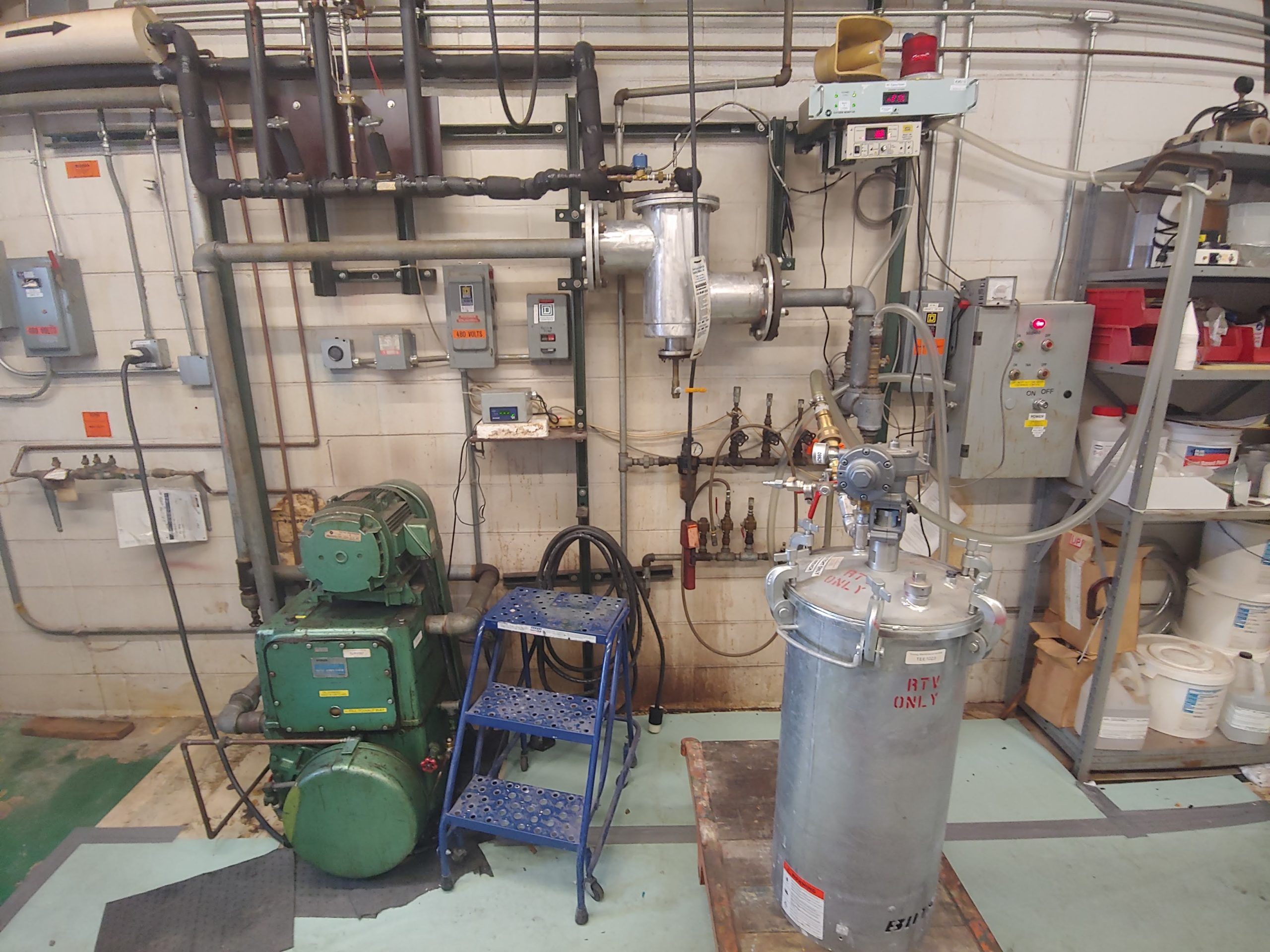
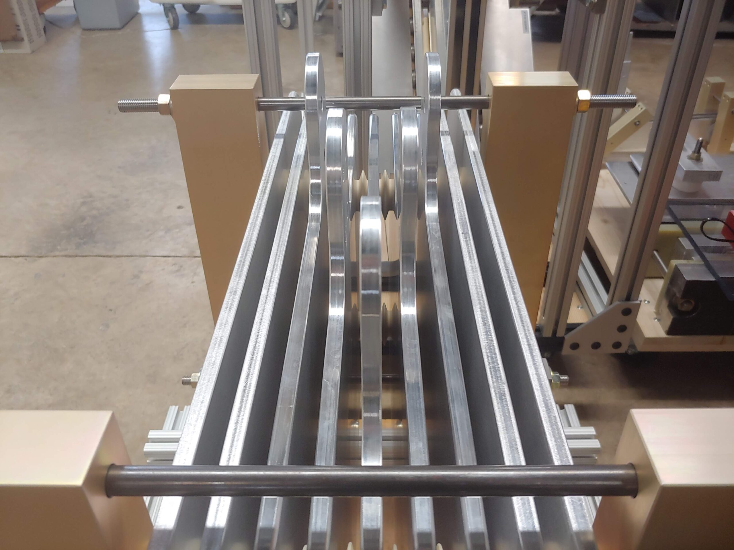
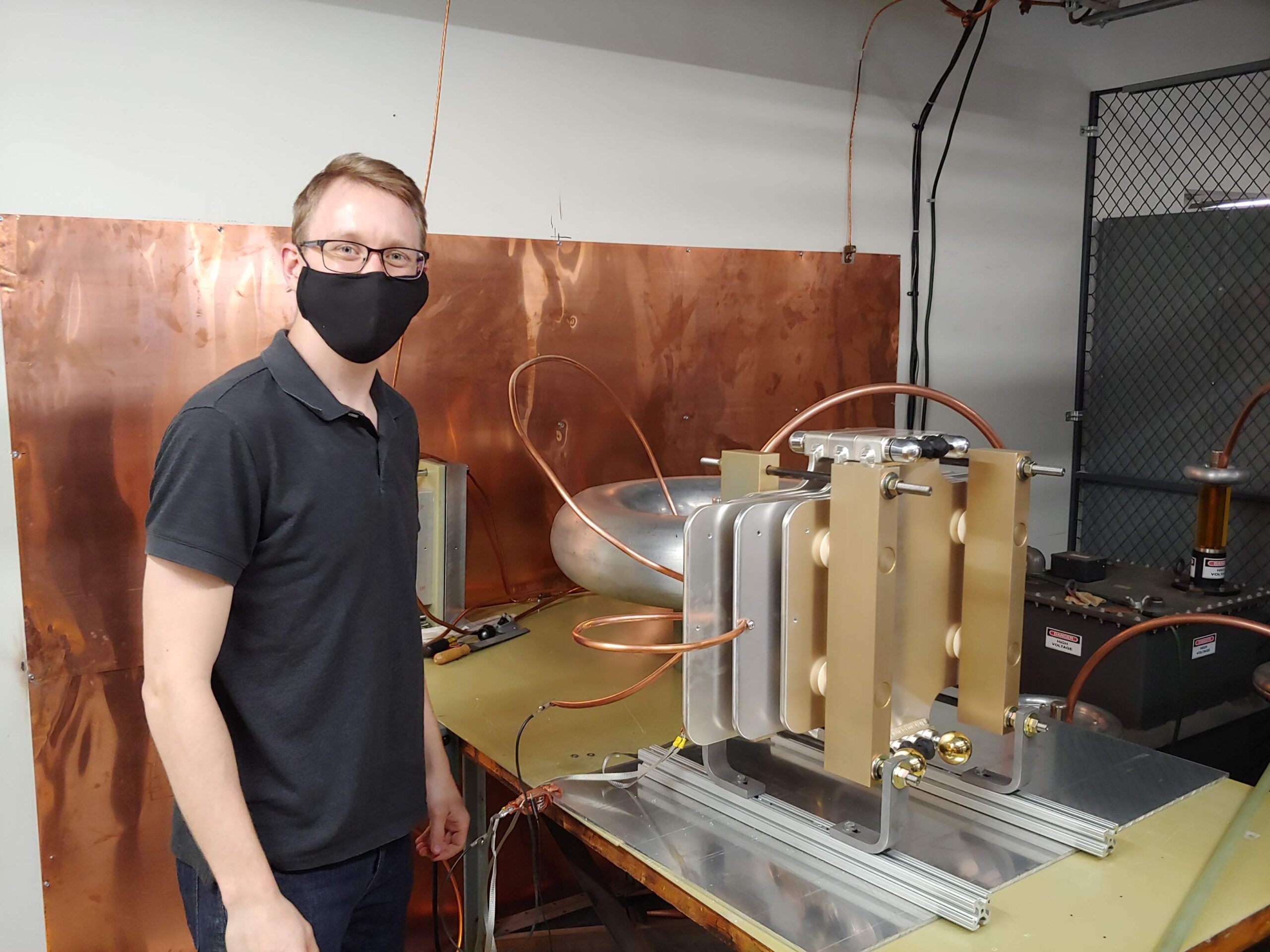
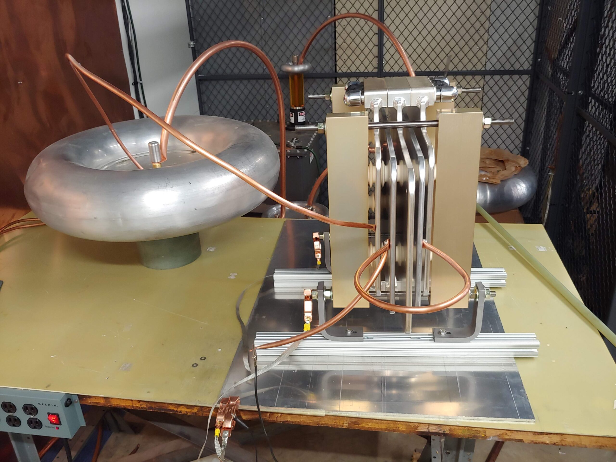
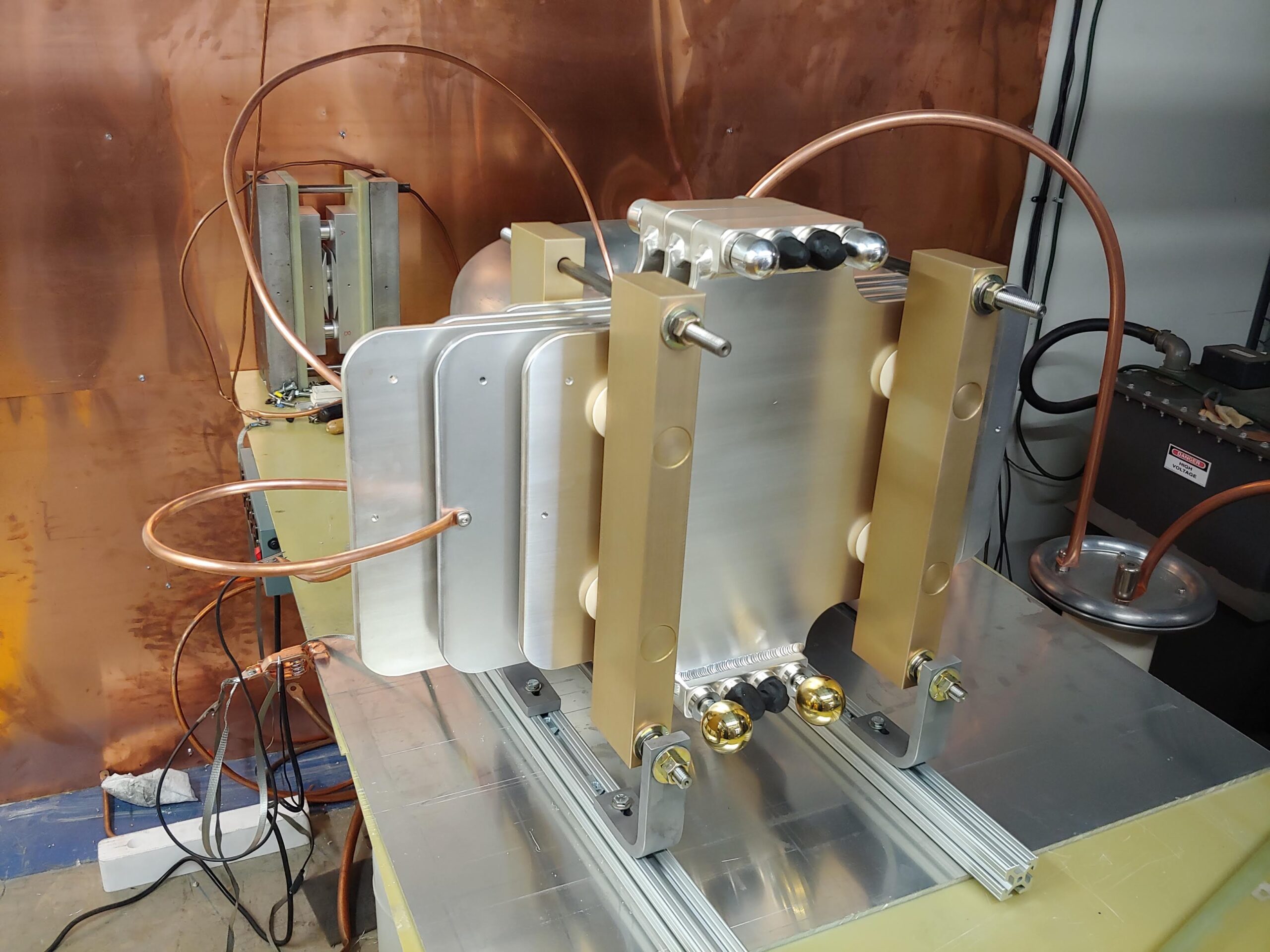
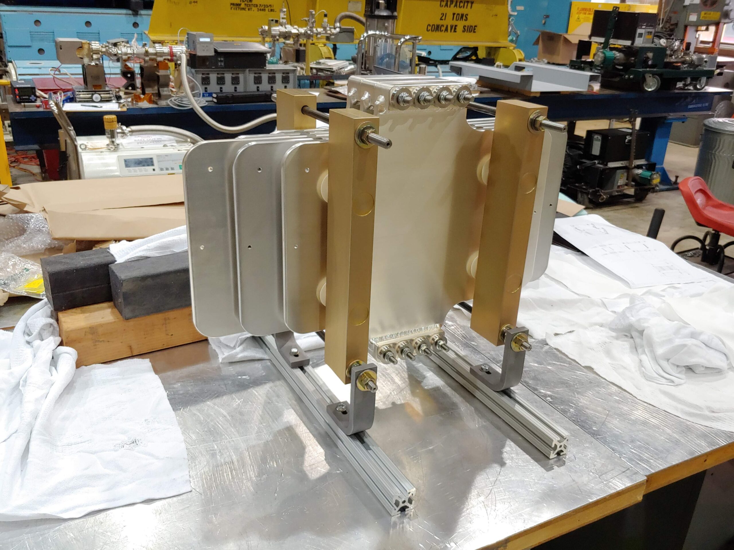
An older lower voltage stripline for the NuMI experiment using eight conductors can be seen in the pictures above. The other picture above is my design for the LBNF pion horn test stand alongside the 16 power supplies that generate the 300kA pulses.
For this project I’m responsible for delivering a 65 meter production stripline for use in the LBNF target hall, the 18 meter stripline test stand shown at the top of this page, and all necessary prototypes and analysis to guarantee the performance of these structures. I work within a small team of engineers and drafters where I perform all conceptual and prelminary CAD modeling and engineering analysis to maximize structure lifetime. During the design process I analyze structural, fatigue, vibration, and thermal performance using a combination of hand calculations and FEA tools. As the systems approach final design I direct drafters and other engineers to help finalize all details of the systems and ensure adherence to phsyics requirements.
The model of the unenclosed 65m target hall stripline above shows how the conductors pass through three gas volumes to go from the power supplies to the horns. The power supplies are placed in a normal occupancy room for easy service, while the horns exist in a highly radioactive nitrogen environment. One of my favorite tasks on this project was figuring out how to get the 5kV conductors through the wall, but keeping the radioactive nitrogen where it belonged.
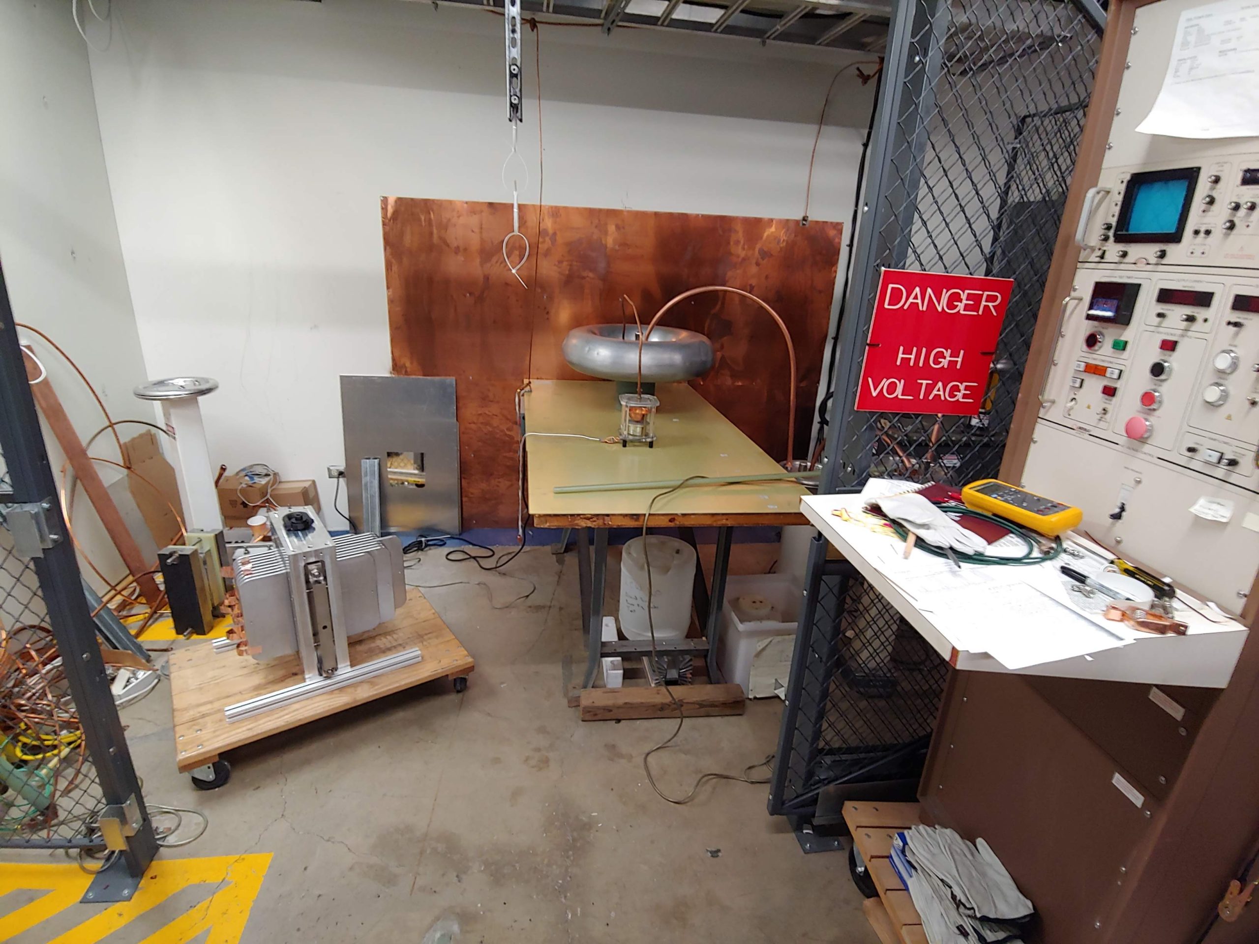
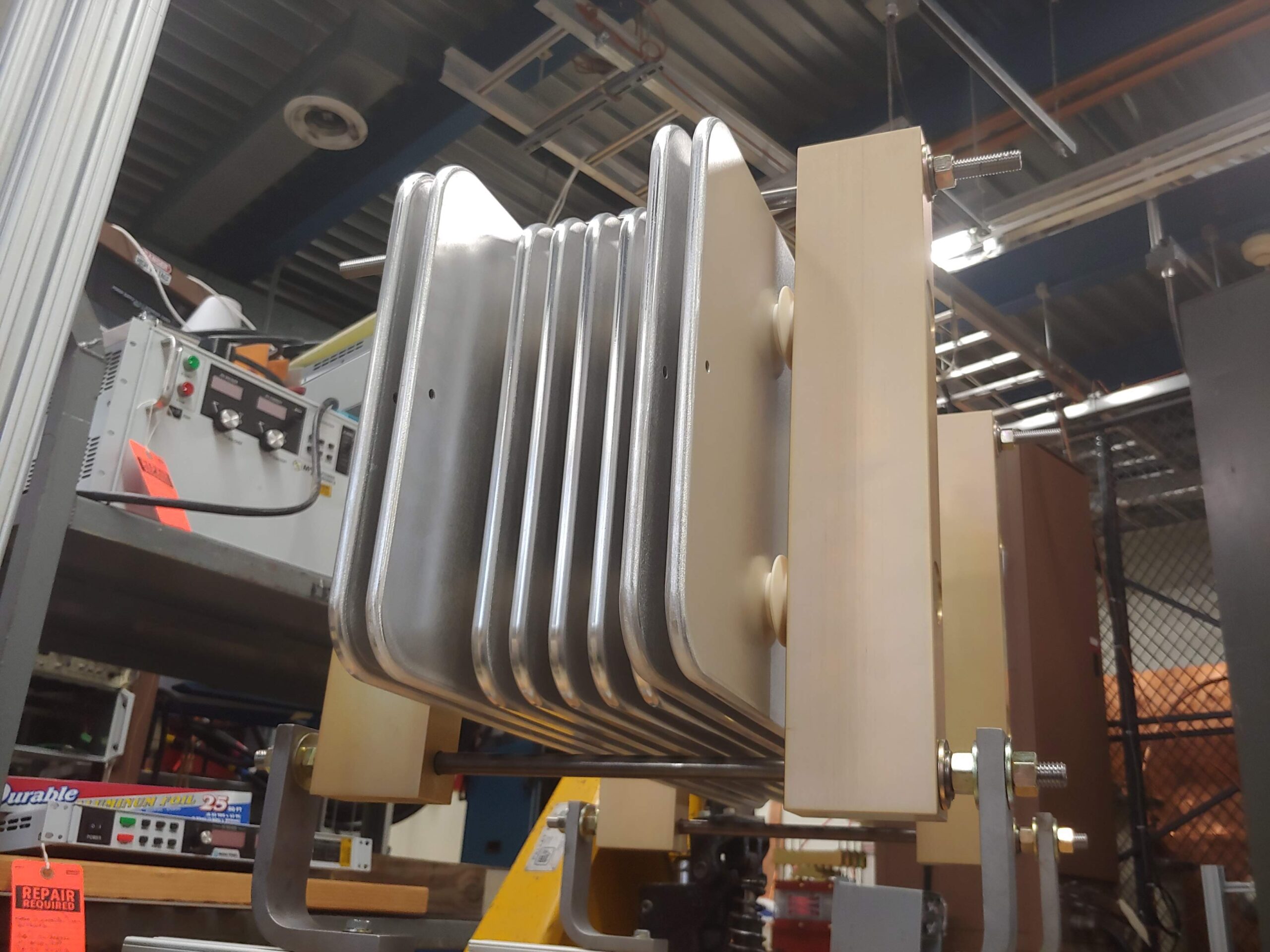
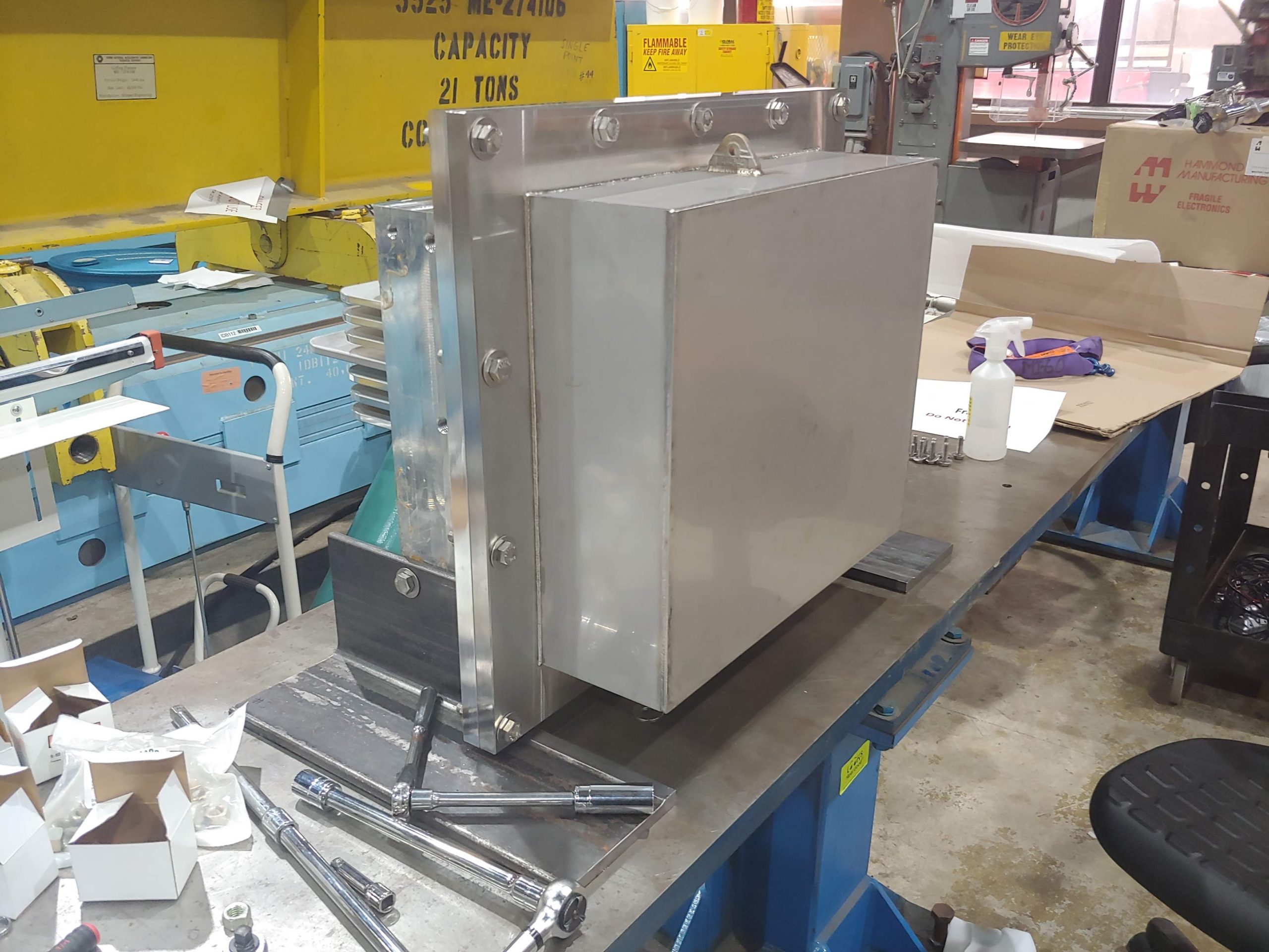
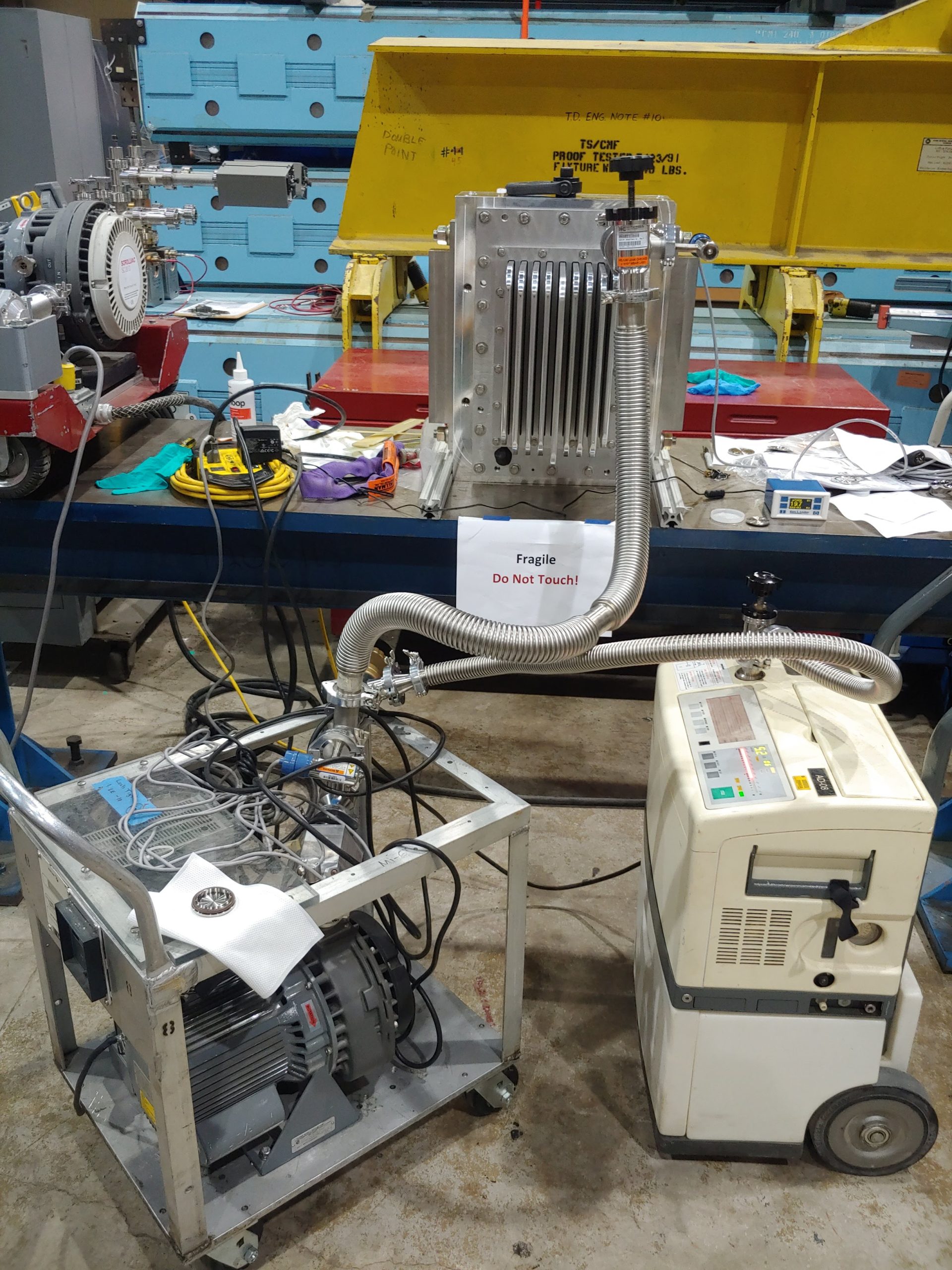
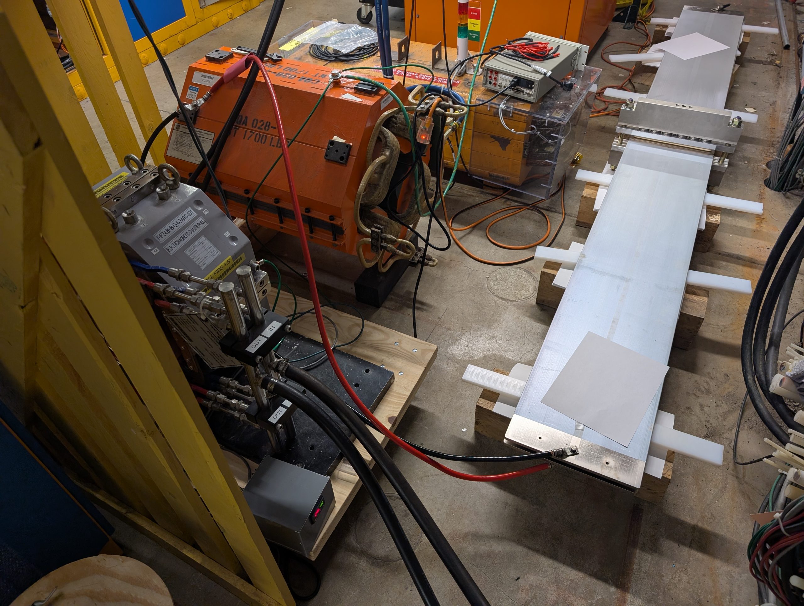
I designed and prototyped the high voltage feedthrough shown above that uses silicone potting to create an airtight seal. The most interesting challenge was that the high voltage conductors are so close to the low voltage conductors, the surface along the silicone between them will ionize and conduct electricity. To solve this I increased the path length between the conductors by molding silicone ribs around each one. This prototype, and several others I designed, had their performance verified using a voltage test stand where each design was energized to over 15kV to check for arcing and corona discharge. I also verified the seal of the feedthrough by fitting an air-tight chamber to one side and pressurizing it with nitrogen for a week, then recording the pressure drop.
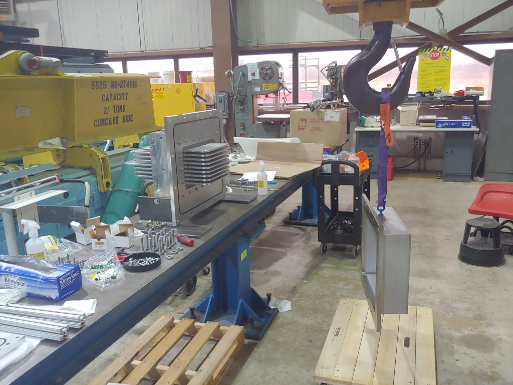
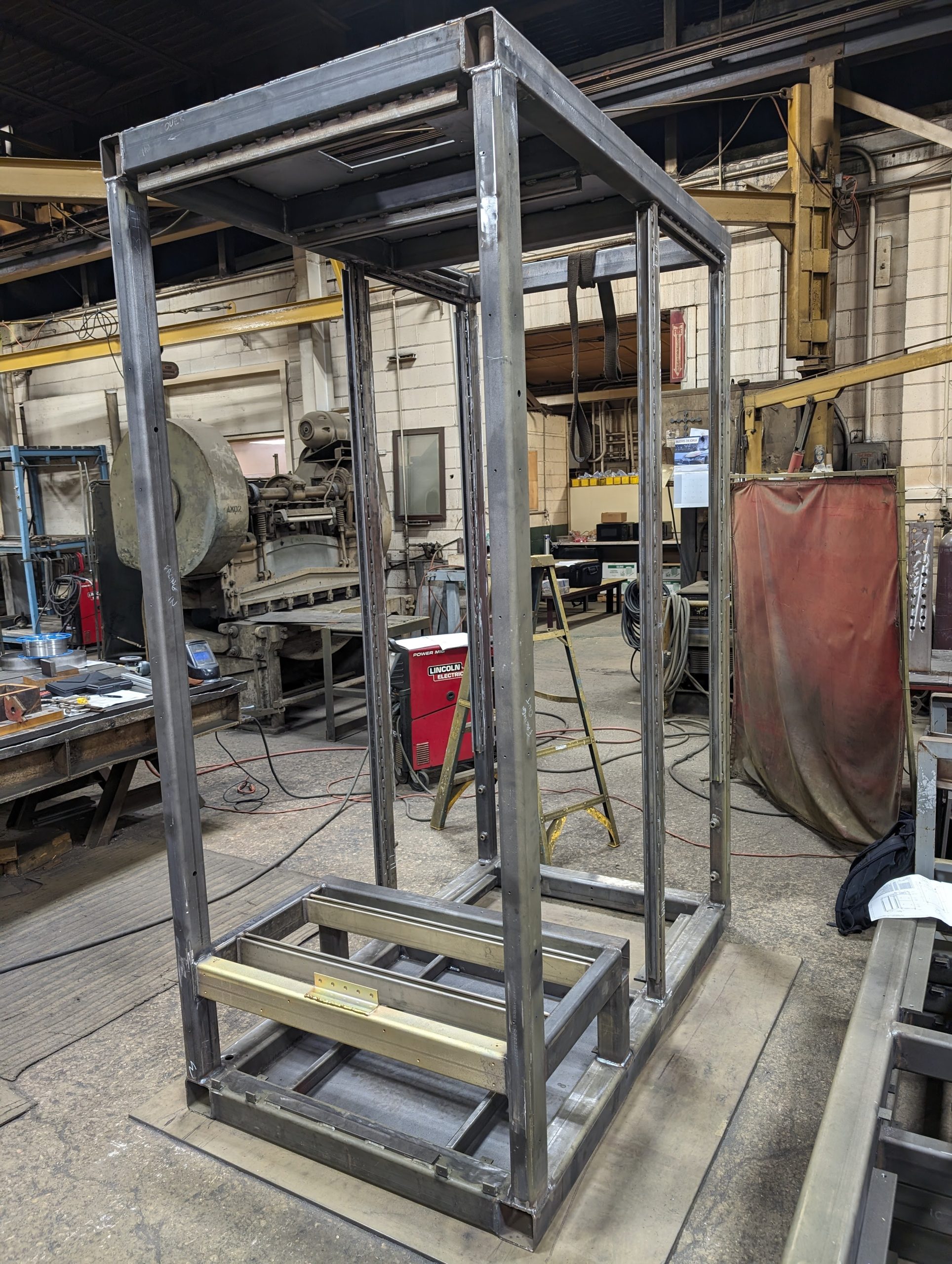
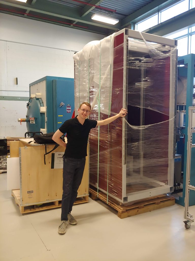
During the project I helped the power supply electrical engineering team by providing structural analysis of the steel cabinet frame. I also engineered the lifting points for the cabinets so they could be top-picked with a crane and lifted two stories up to their final installation location in the target hall. After analysis was complete, I managed quality assurance of the cabinets to make sure all structural welds were to print and dimensions within spec. Additionally, I managed mass properties to ensure the center of gravity location met safety requirements.
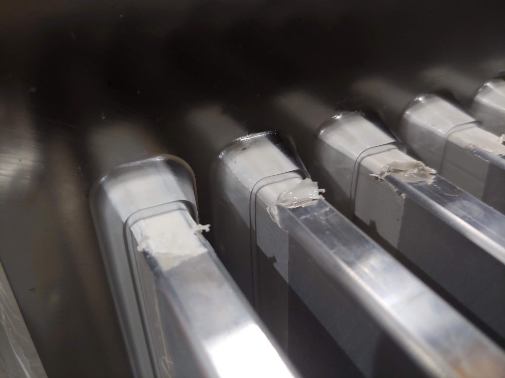
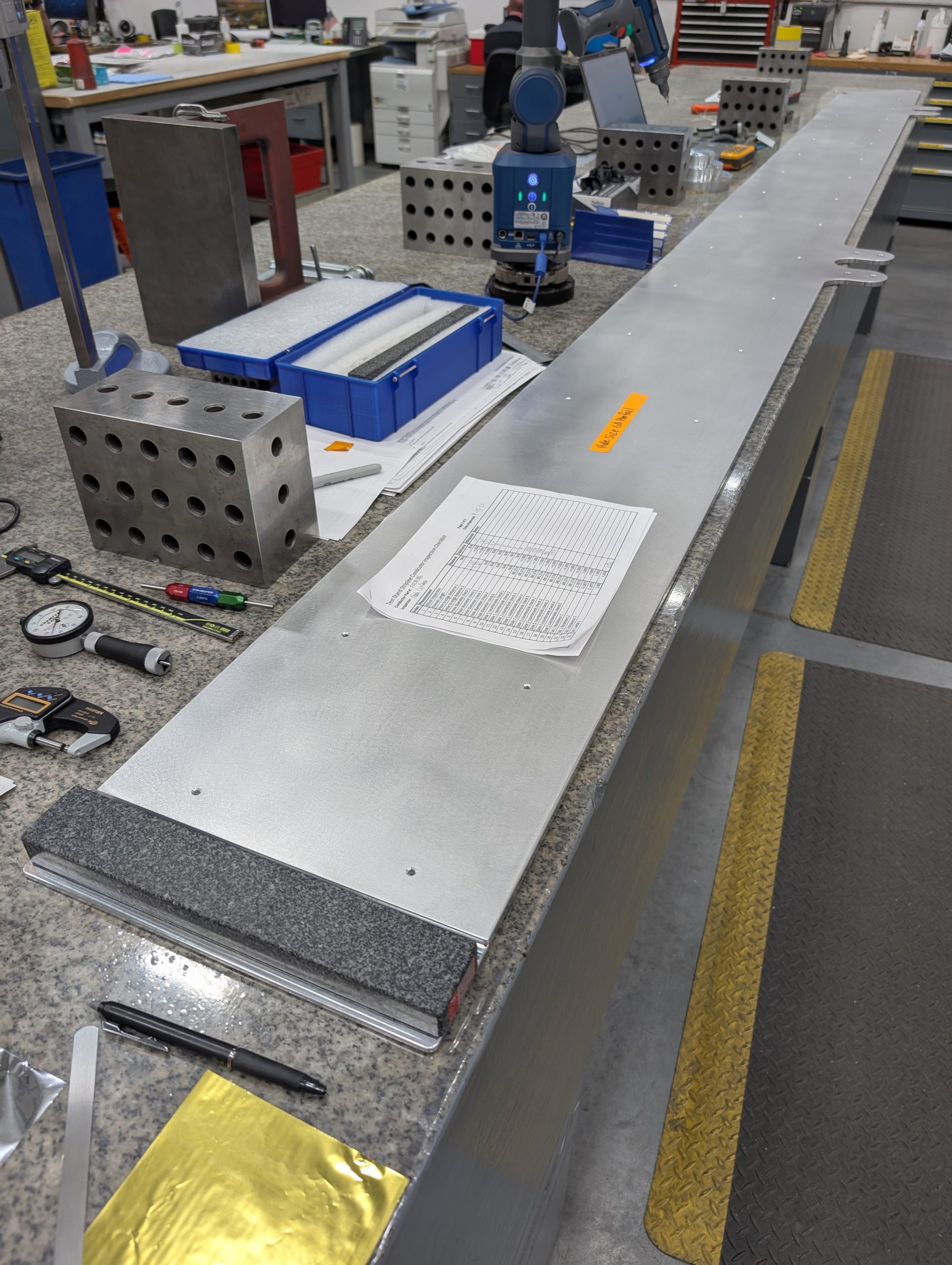
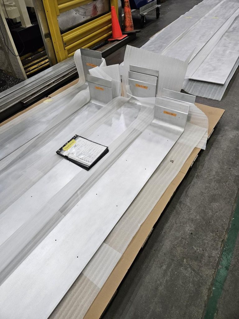
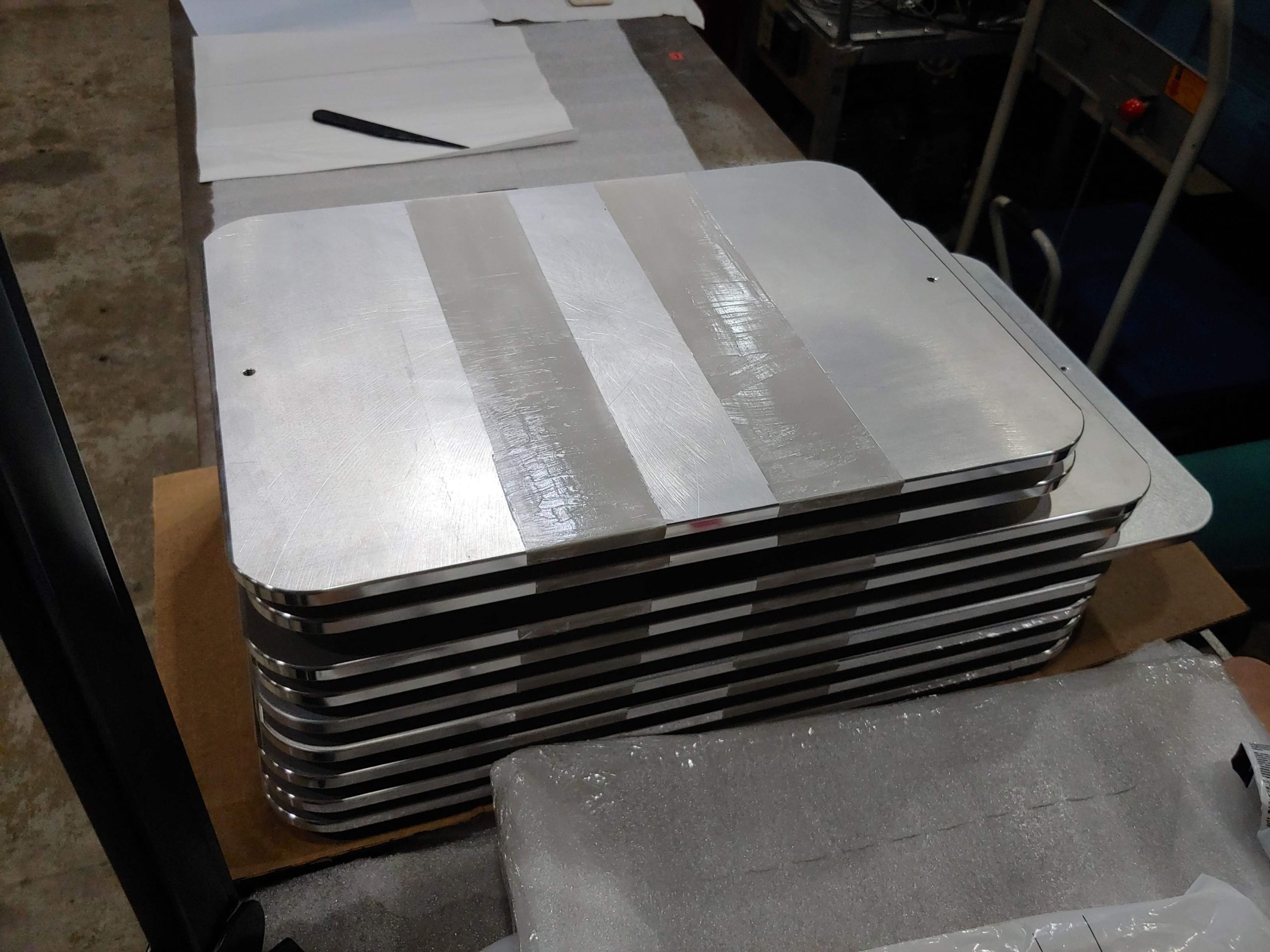
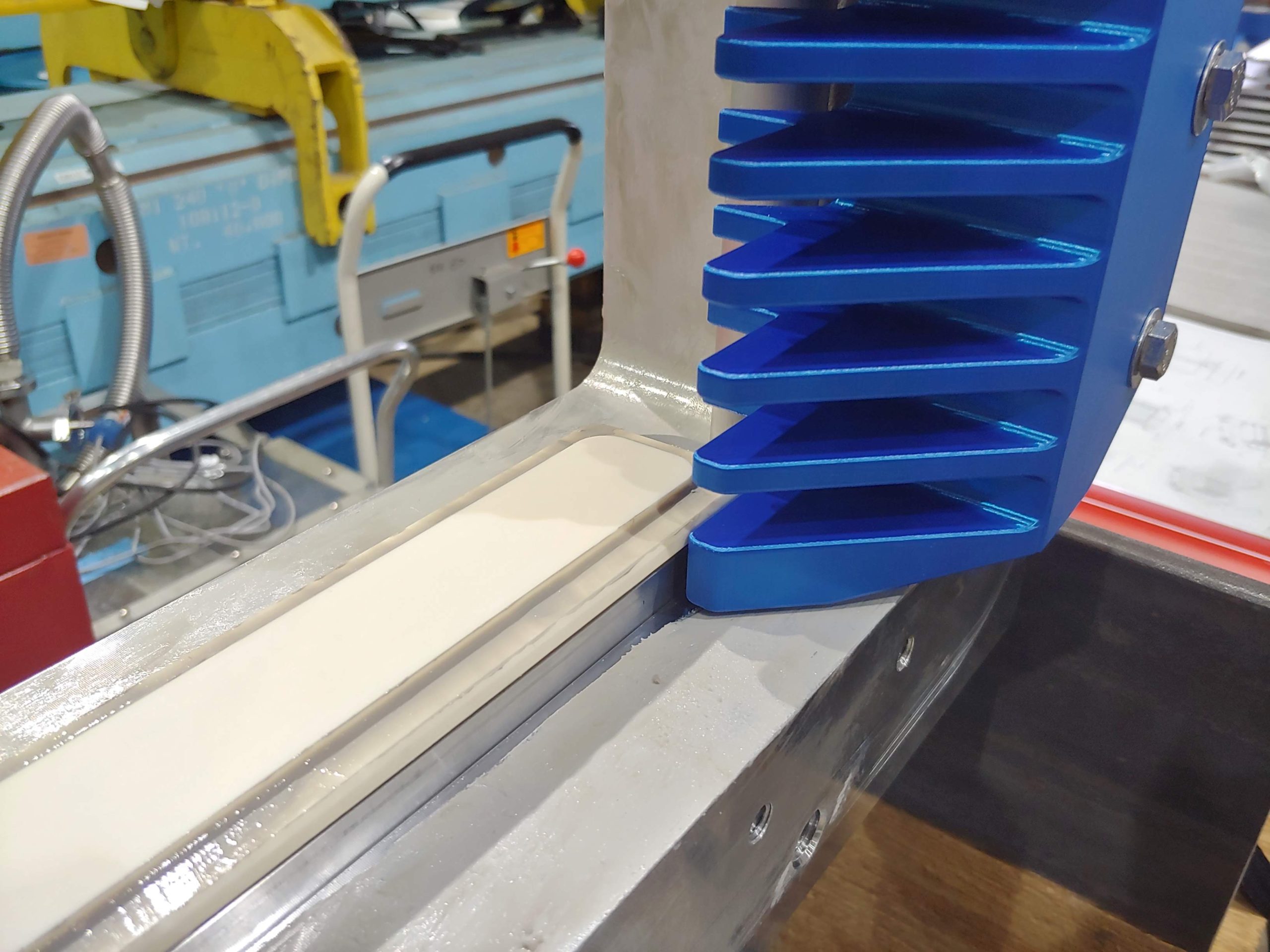
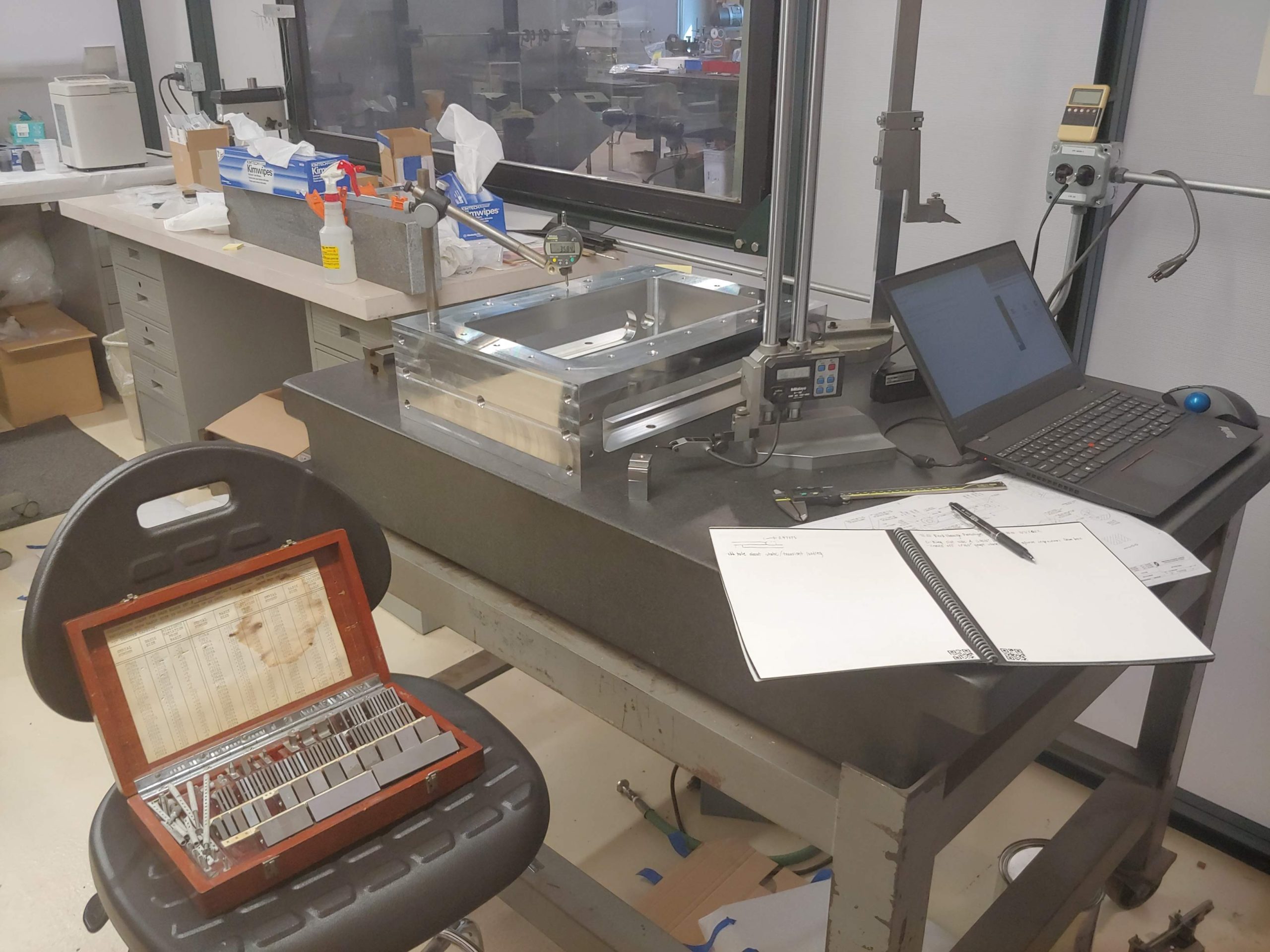
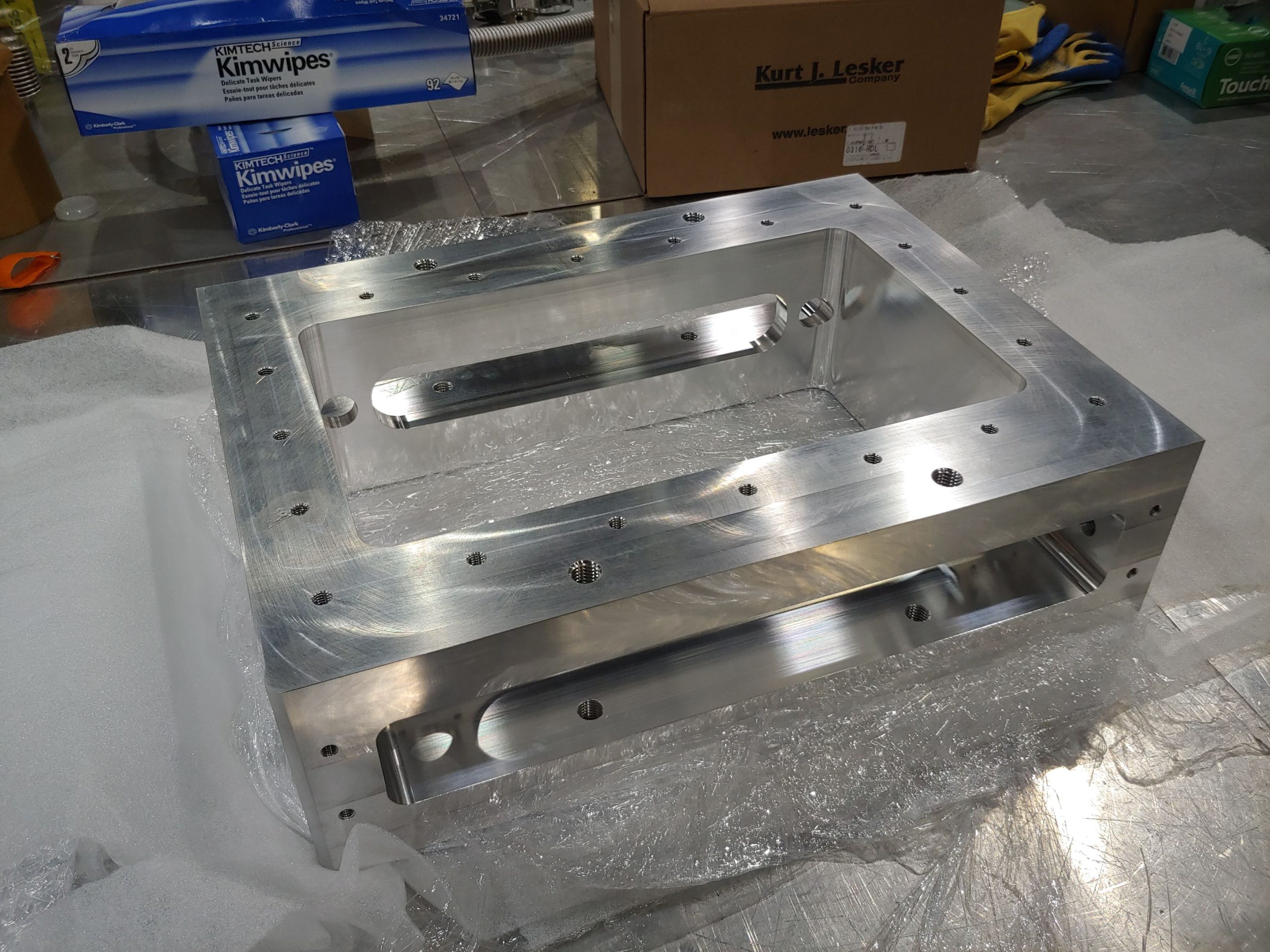
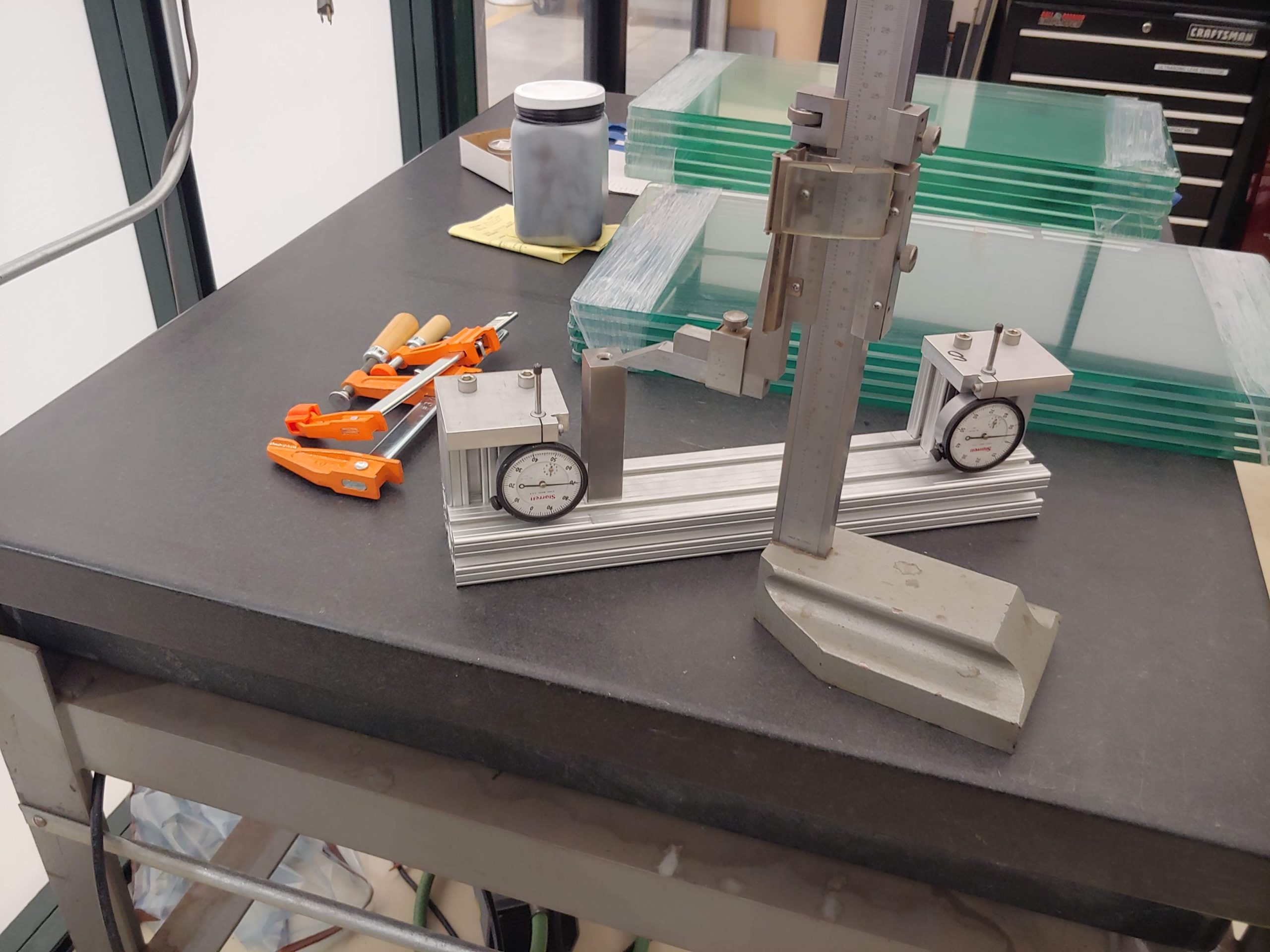
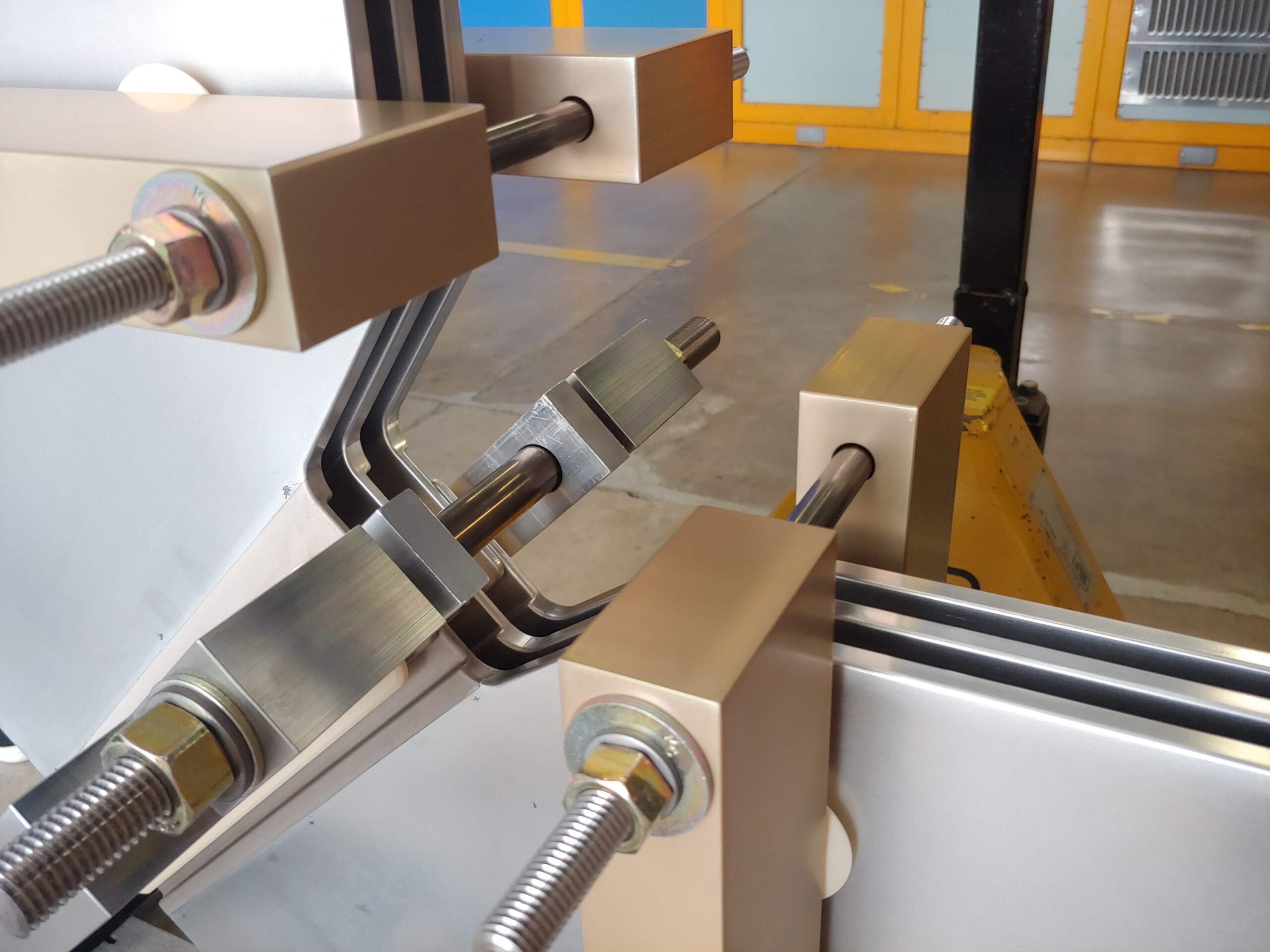
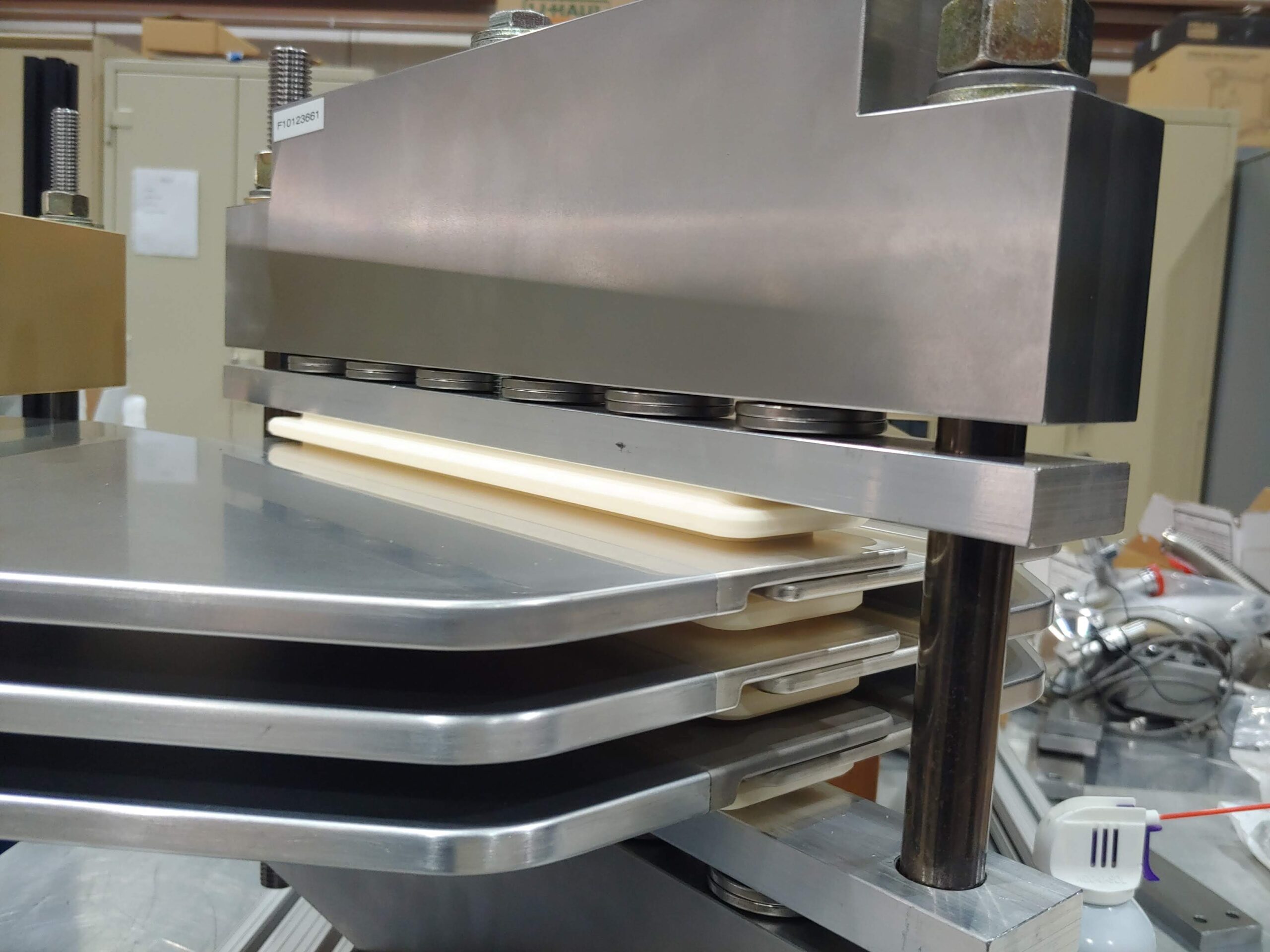
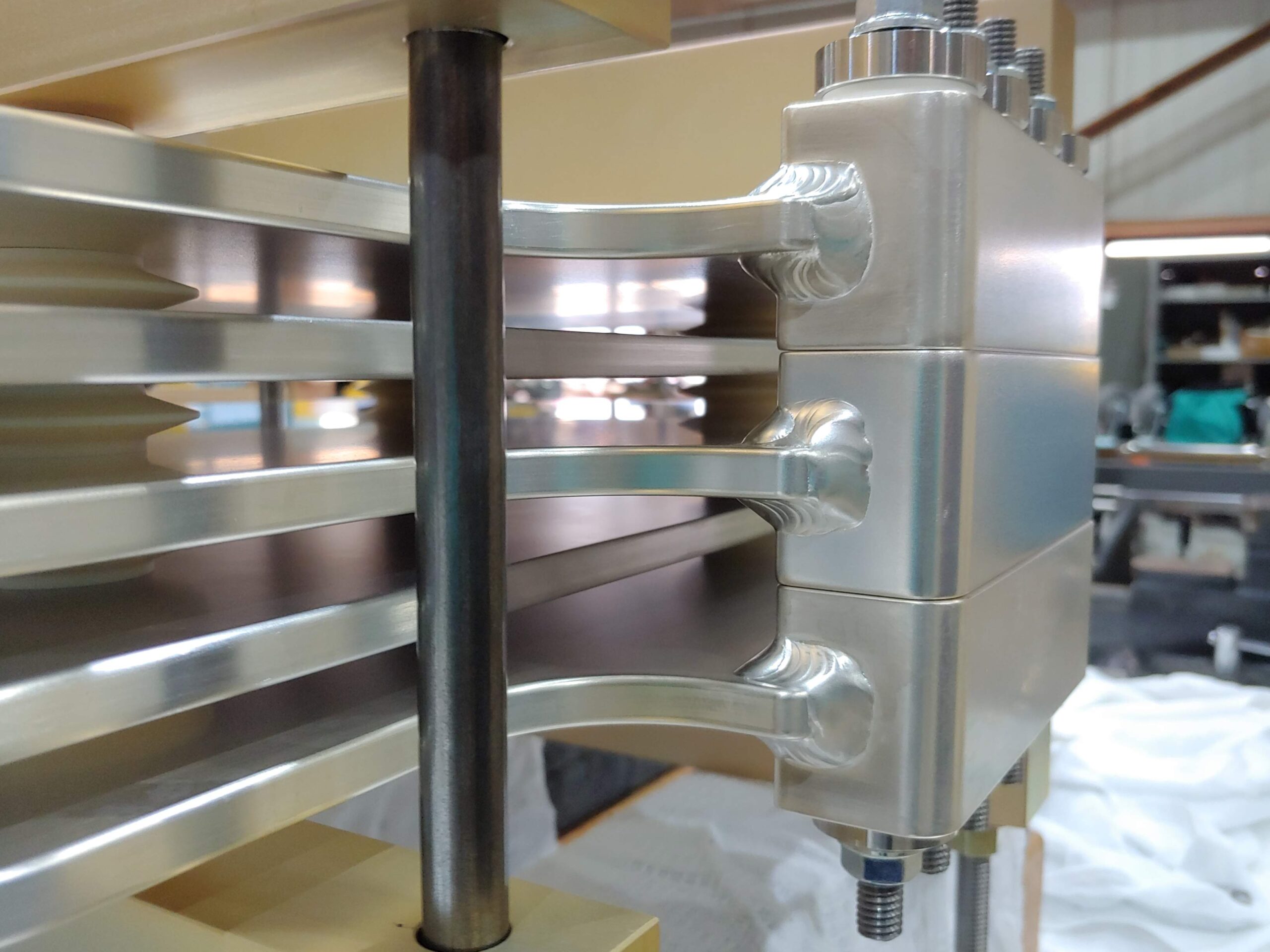
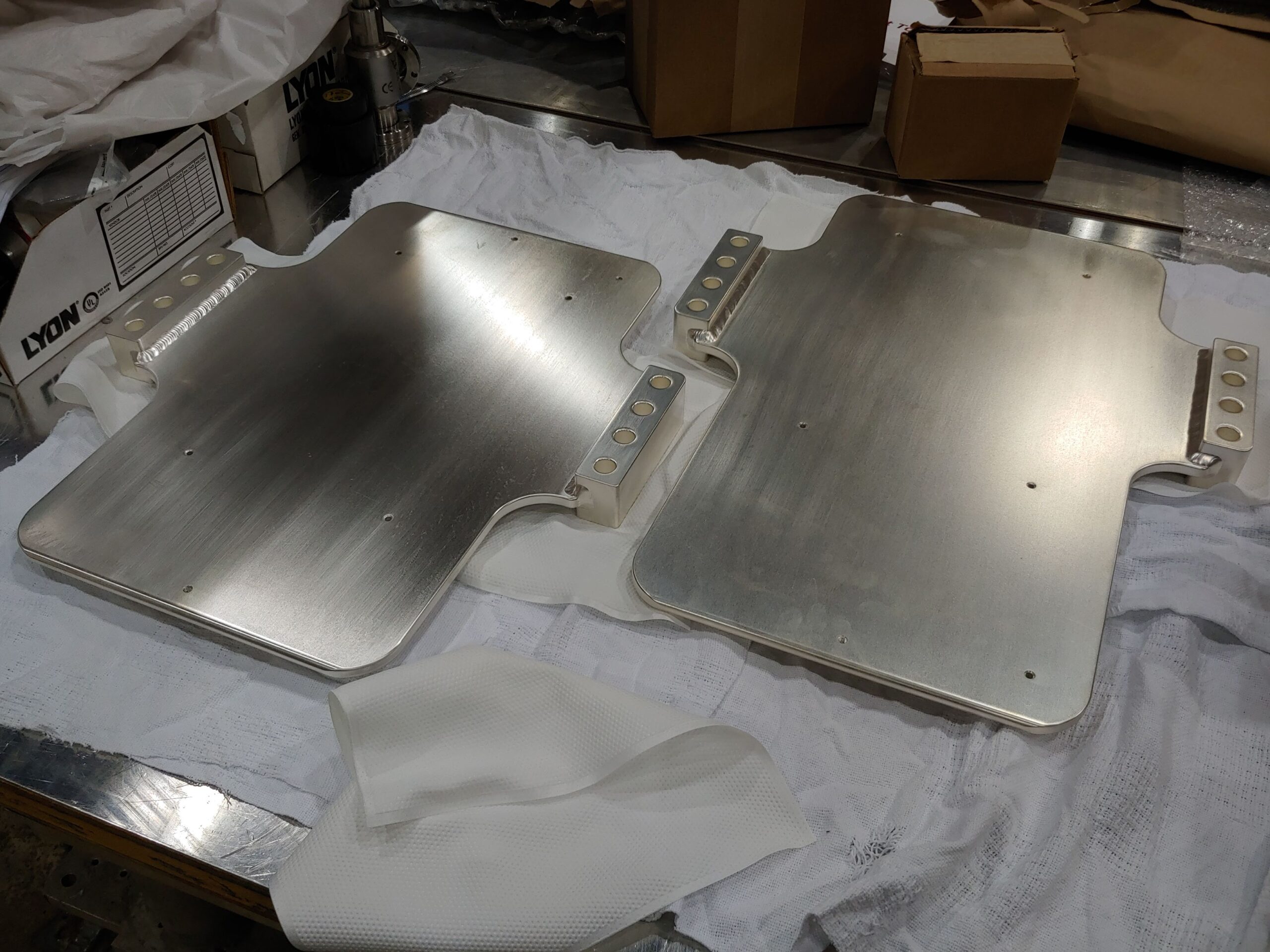
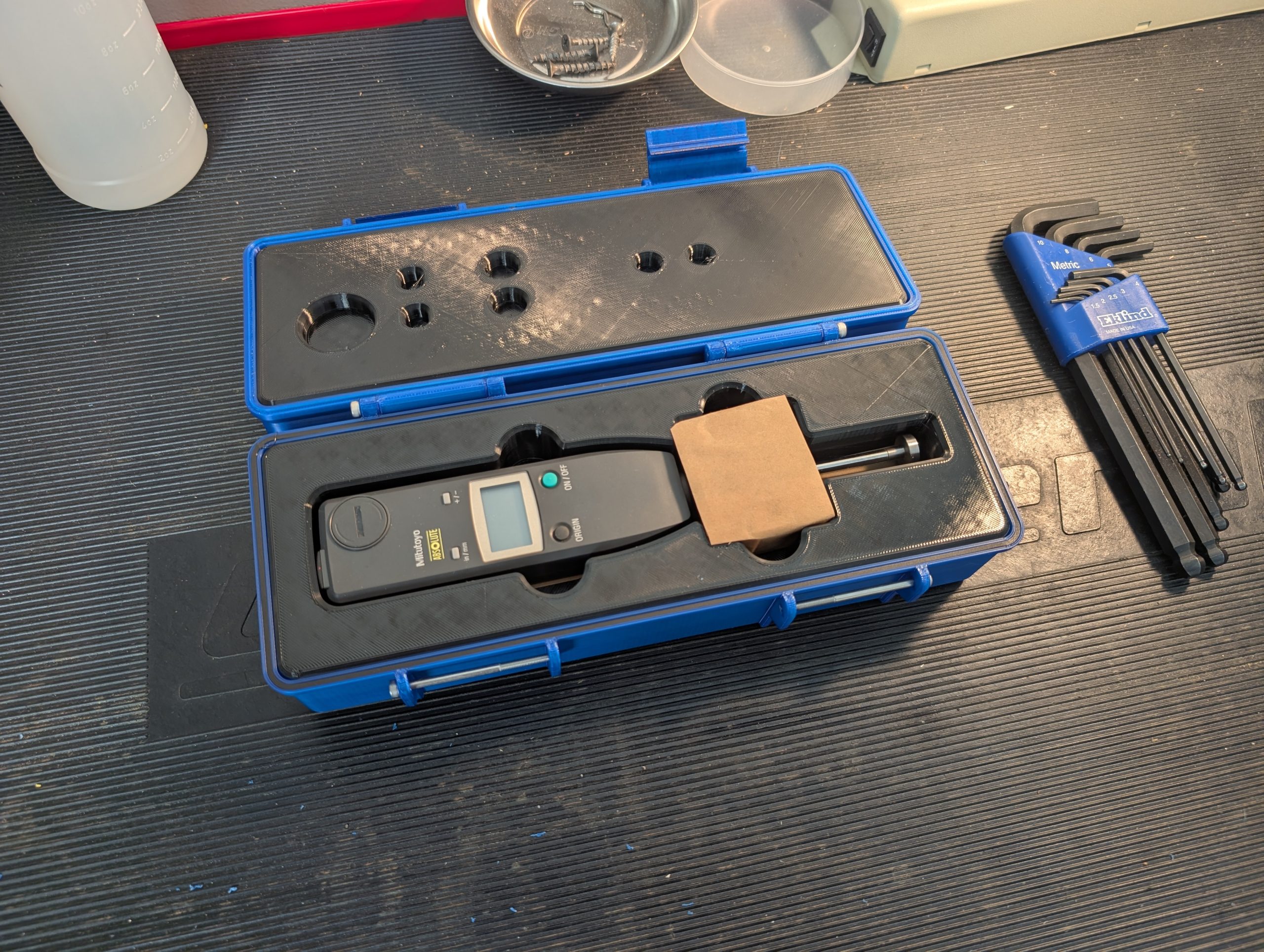
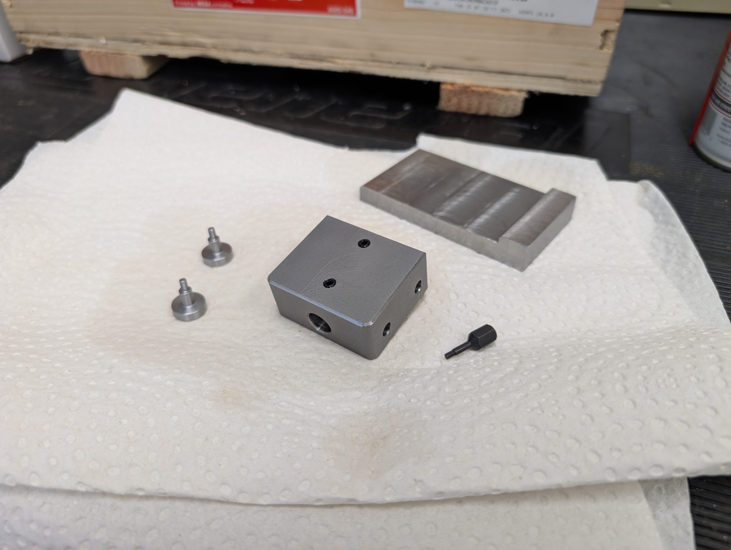
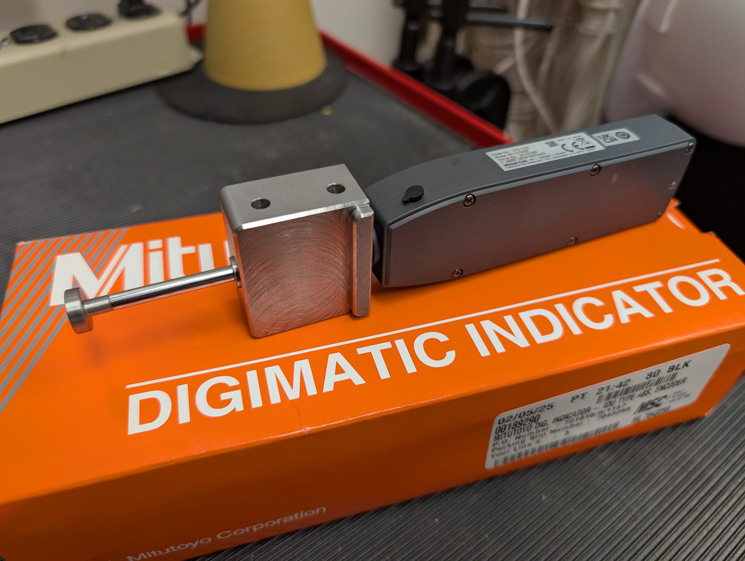
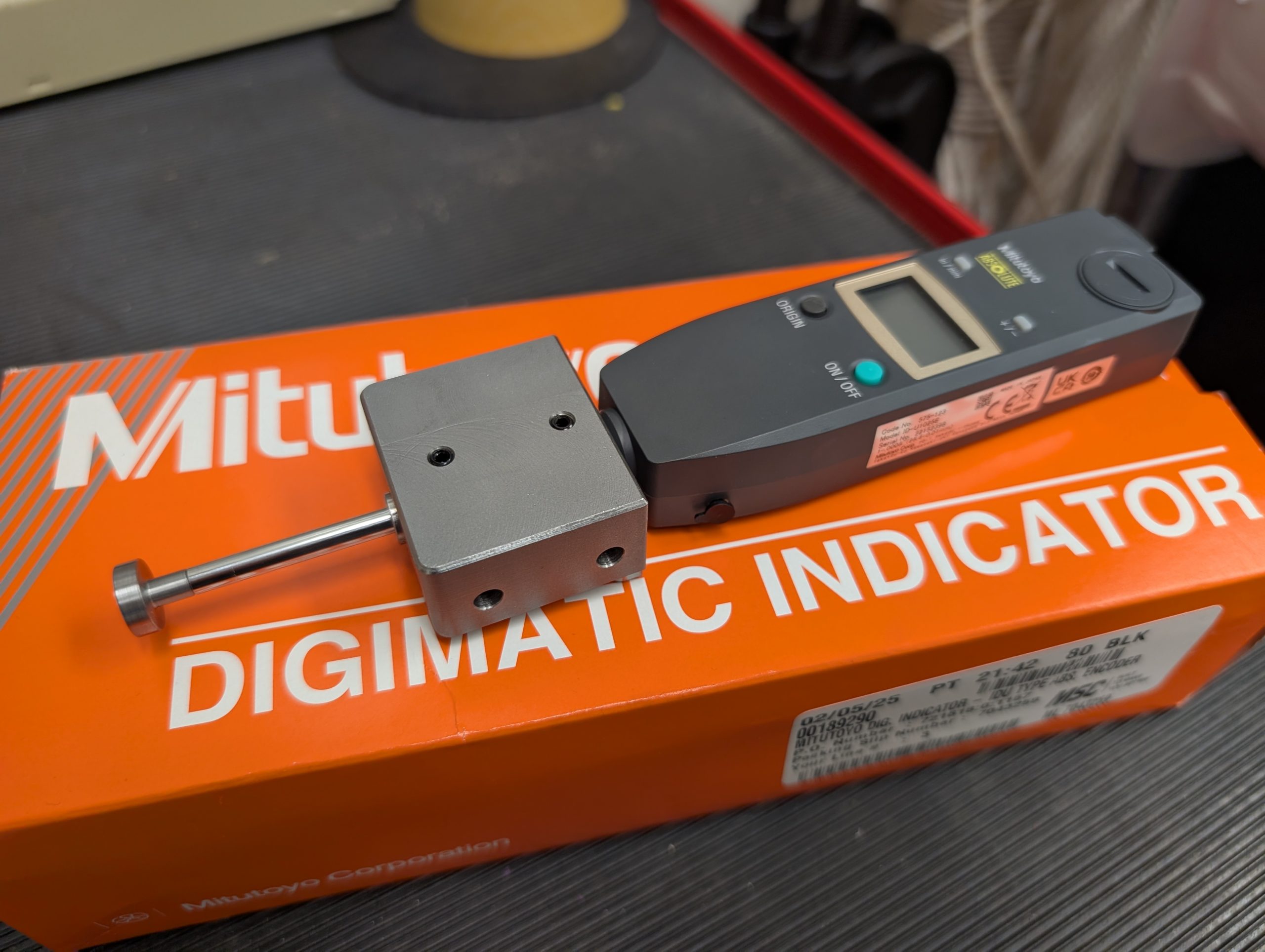
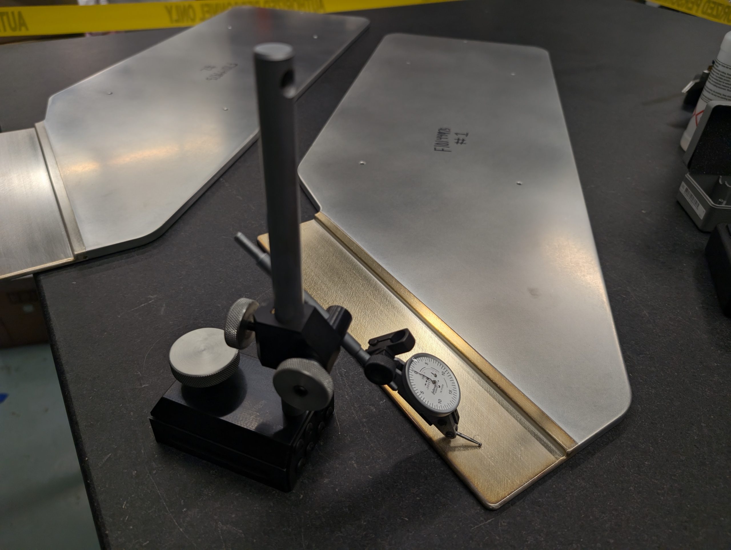
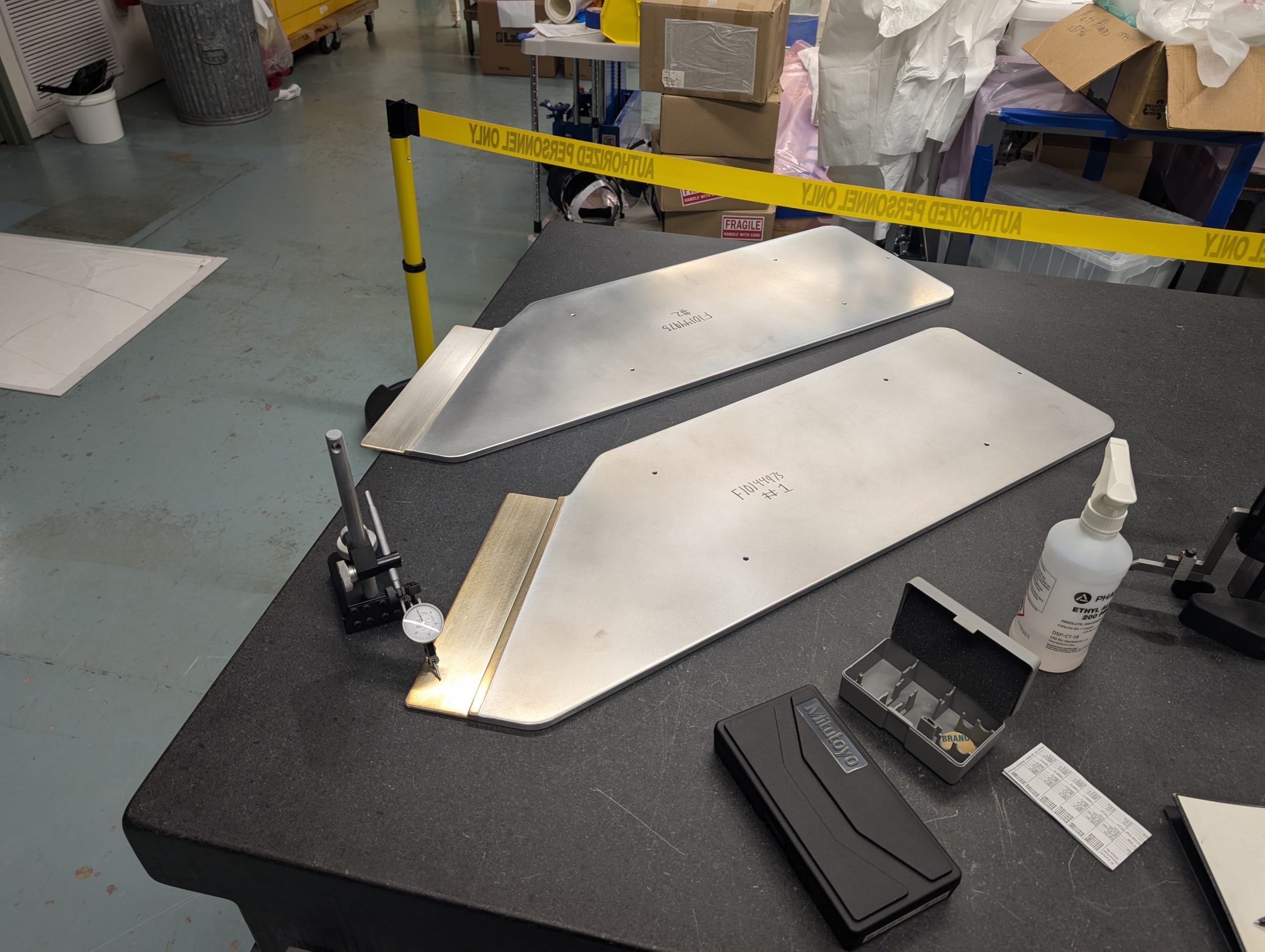
Similar to the power supply cabinets, I also wrote the quality assurance plans for all major stripline components, designed inspection tooling, and traveled across the country to verify all components met our exacting specifications before they moved to the next vendor. Despite the unassuming appearance, the tolerancing and surface finish requirements for these conductors required careful vendor selection and even more careful communication to make sure the vendors knew we were serious!
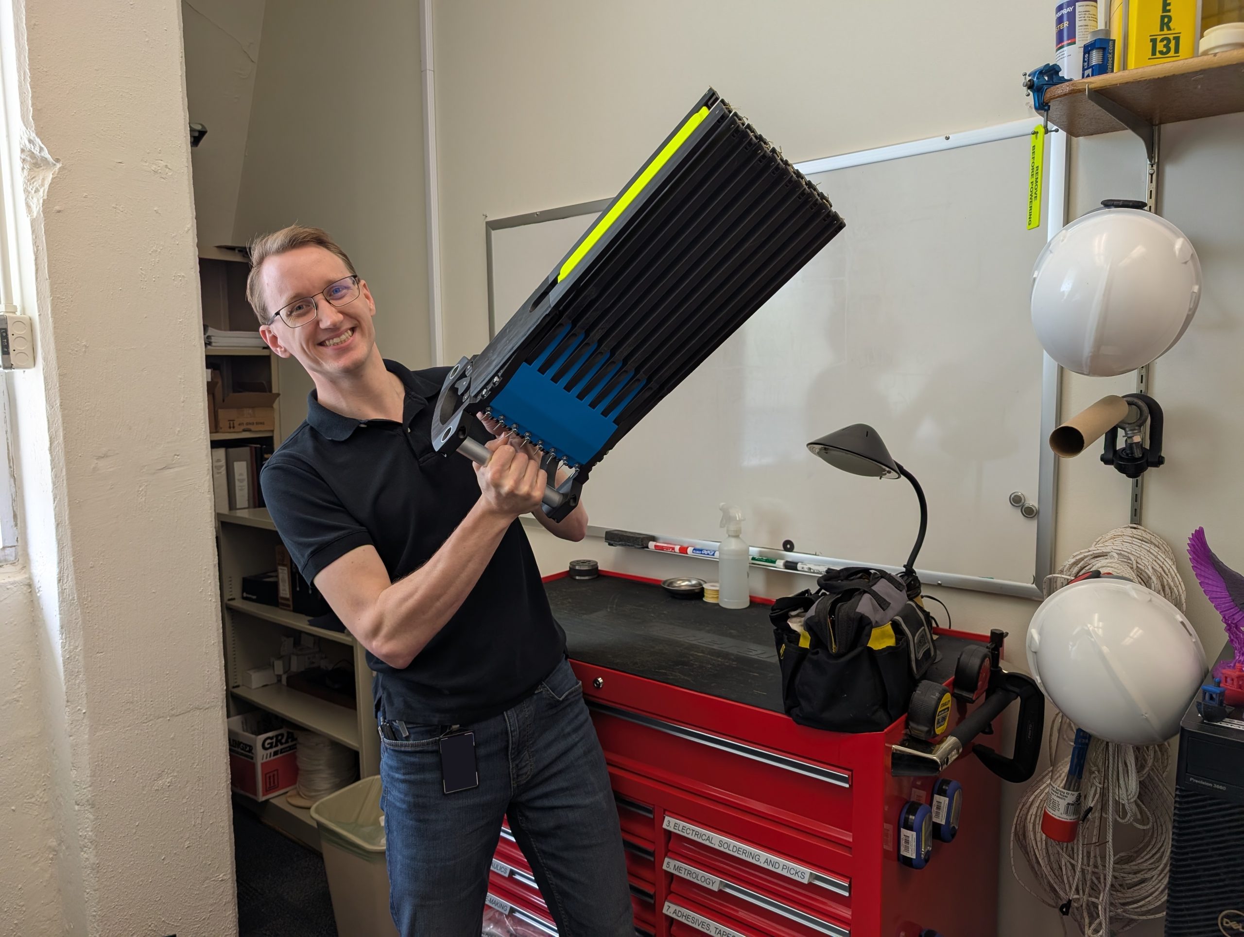
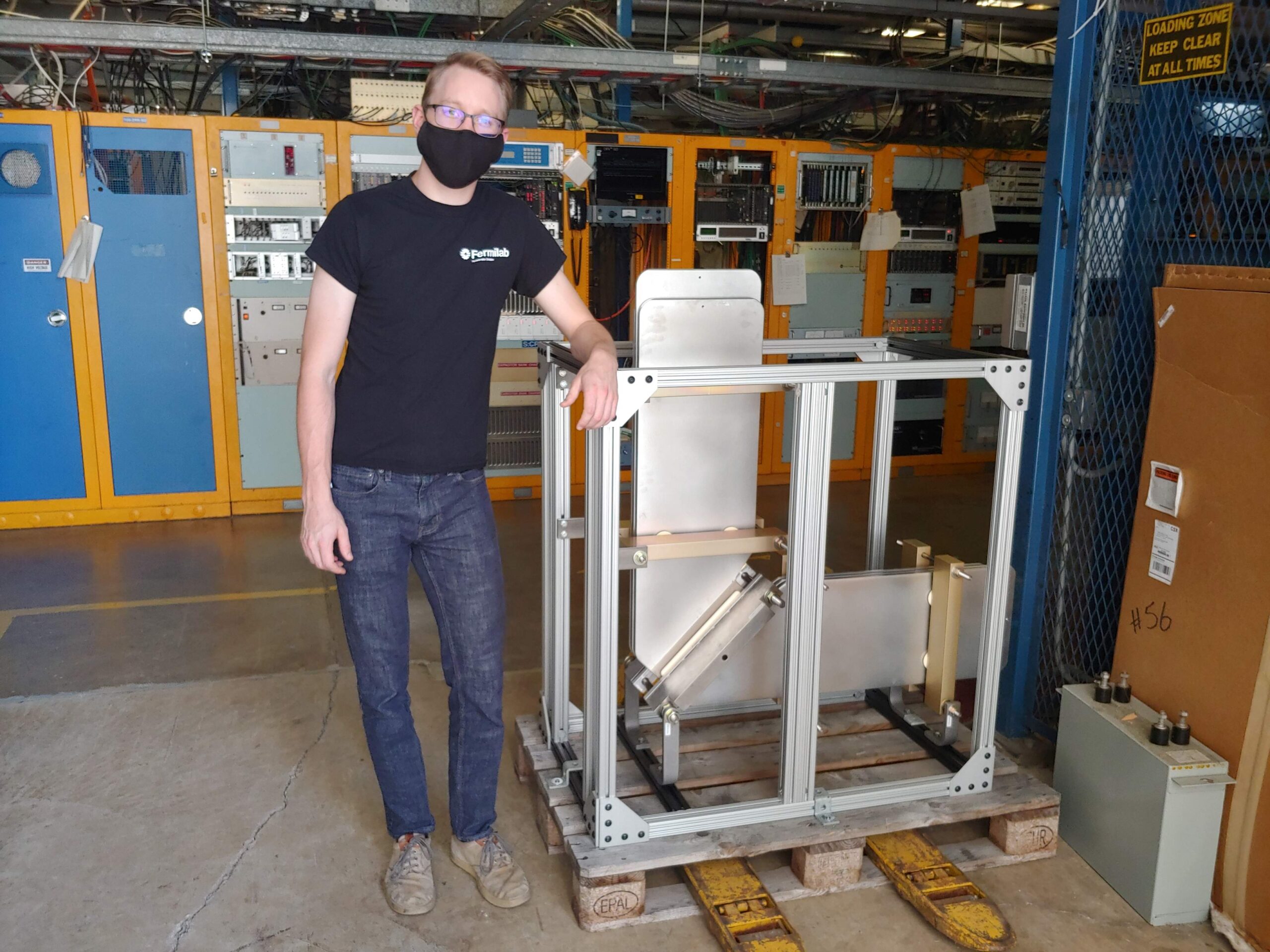
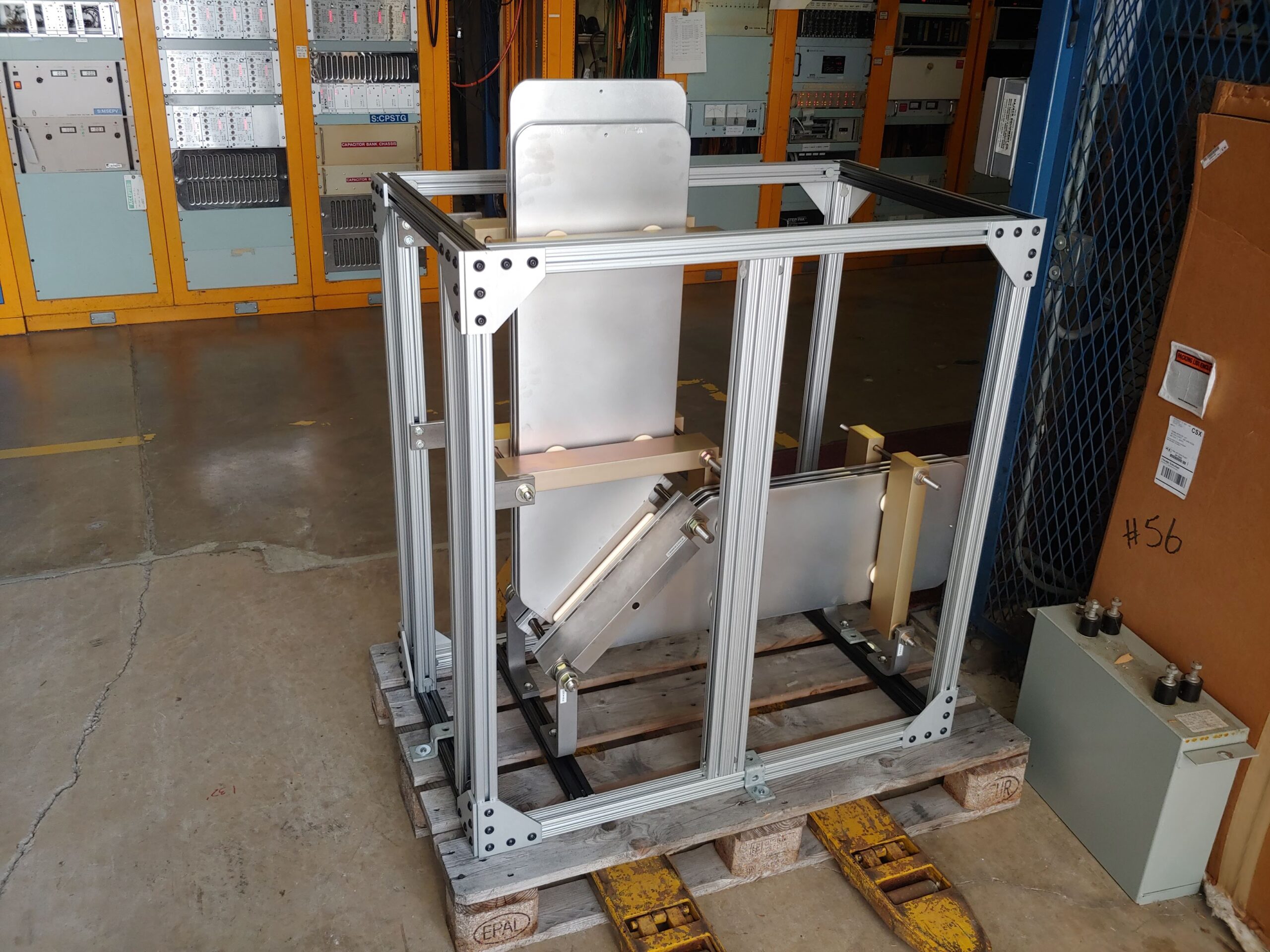
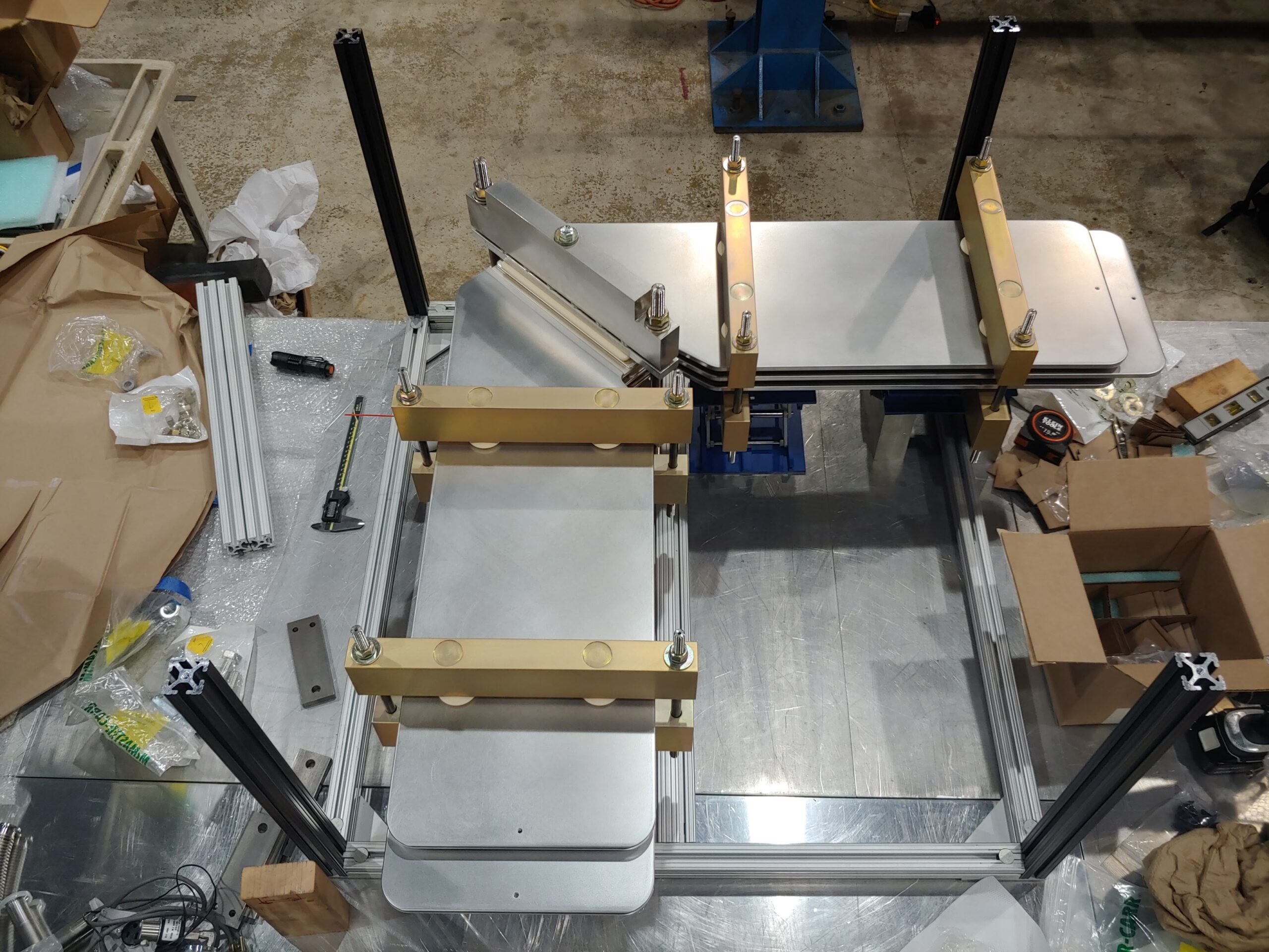
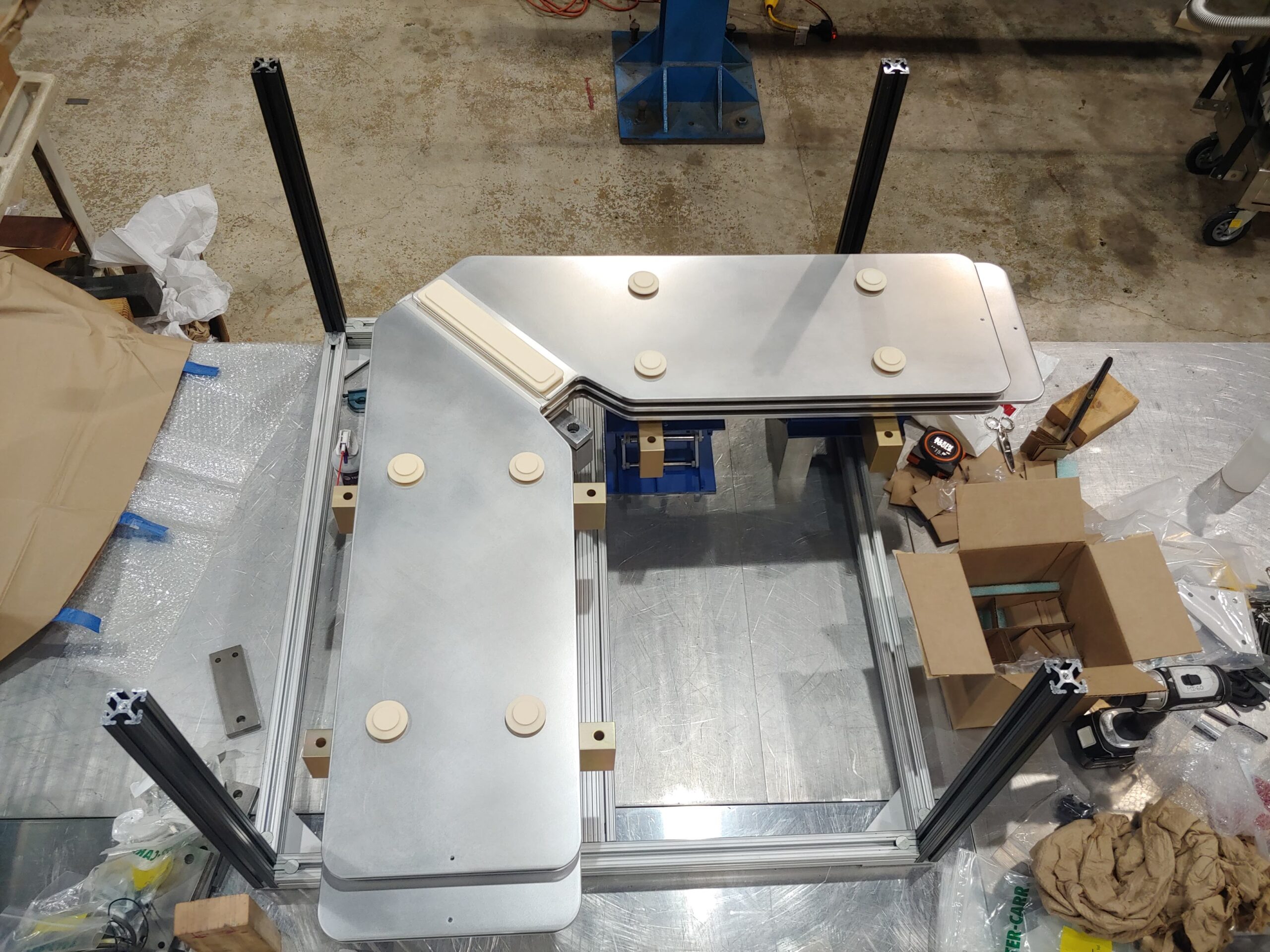
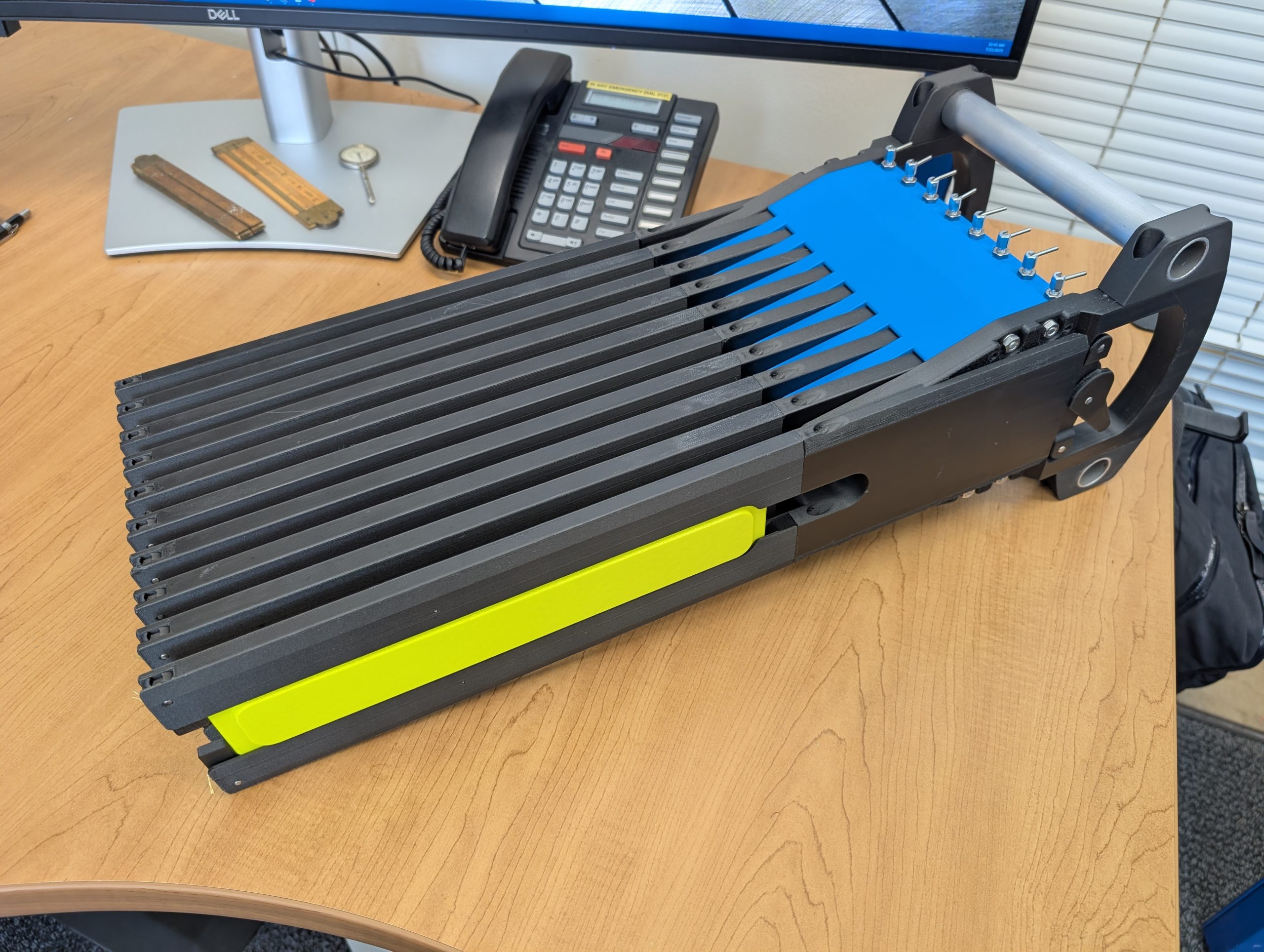
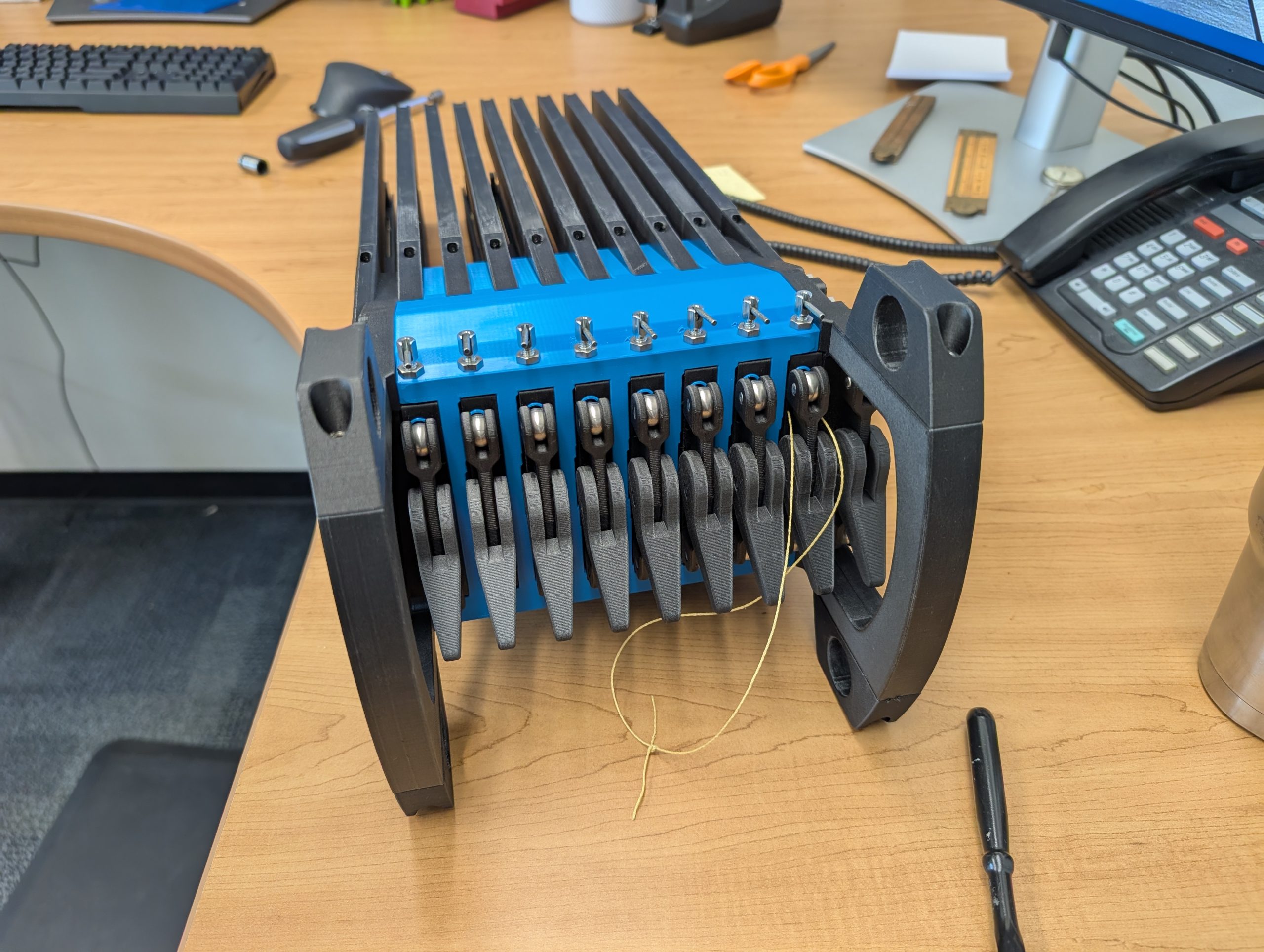
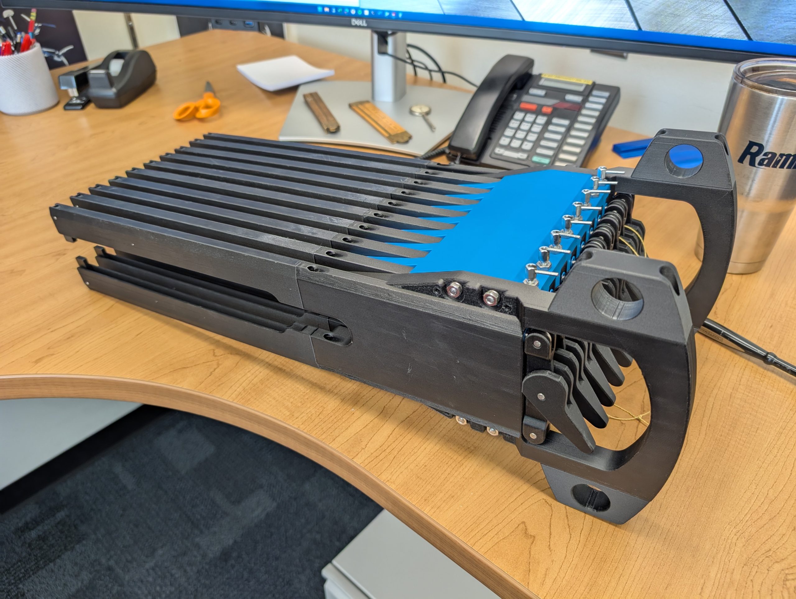
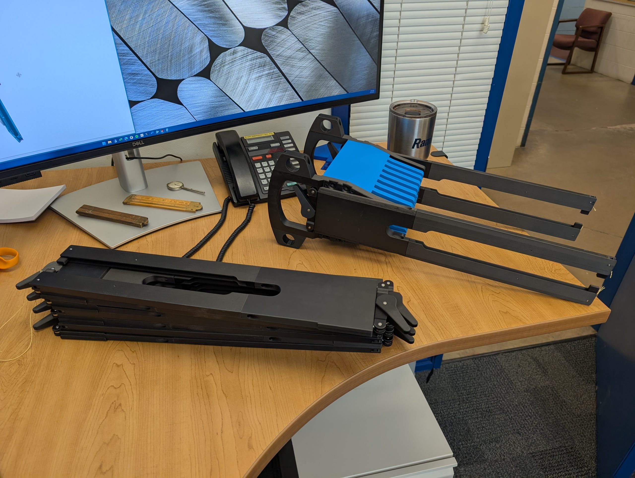
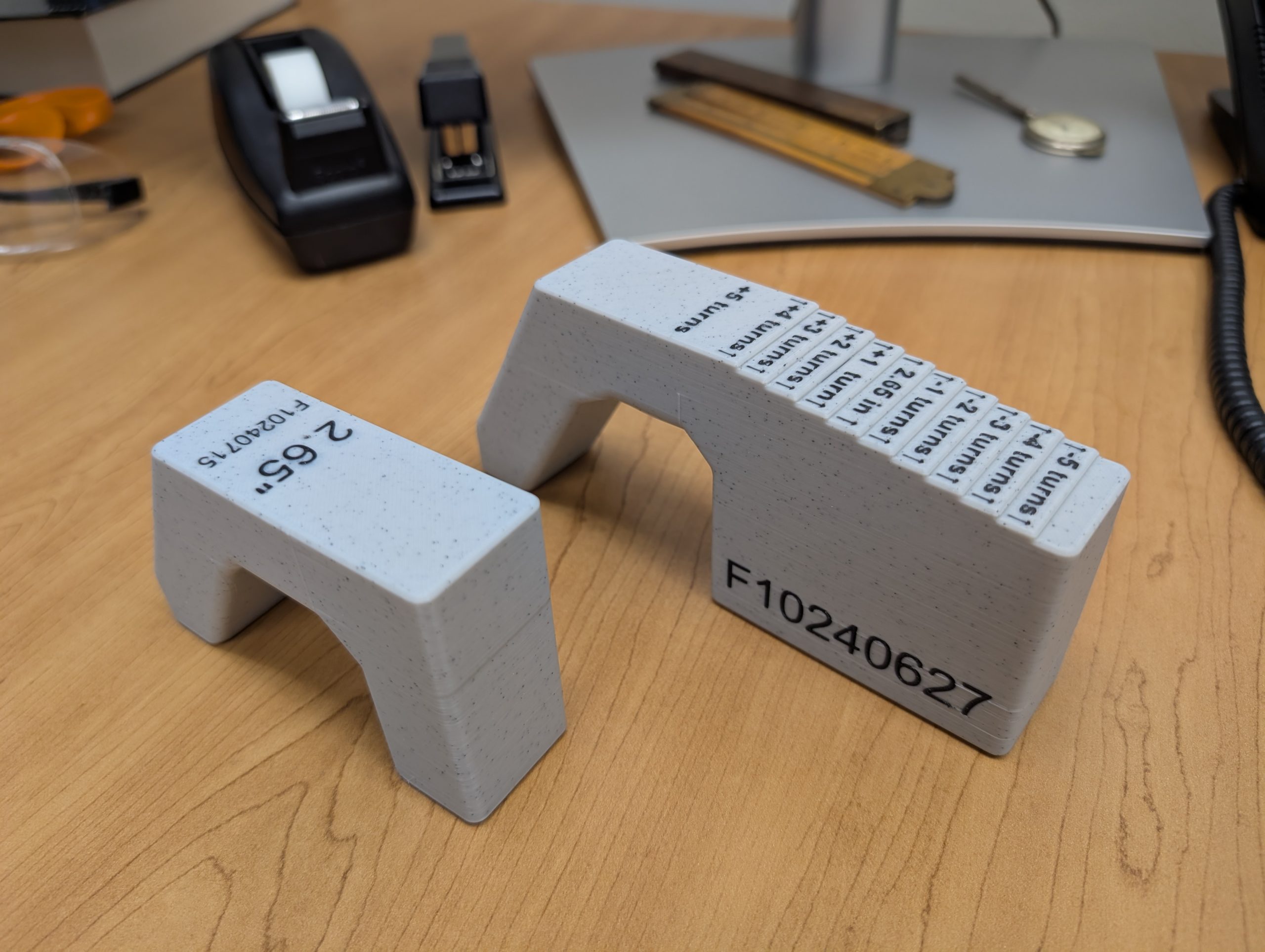
For several challenges on this project I leveraged 3D printing to meet project requirements and reduce costs. The assembly fixture below is designed to allow technicians to quickly install delicate ceramic isolators in high radiation environments. By using a Markforged Mark 2 3D printer to print parts with continuous carbon fiber reinforcement, I was able to create a high-performance, lightweight assembly with no machined parts. The same assembly made from aluminum was going to be over 60 pounds! The 3D printed version by comparison was barely 25 pounds thanks to lightweight plastic and partial infill printing.
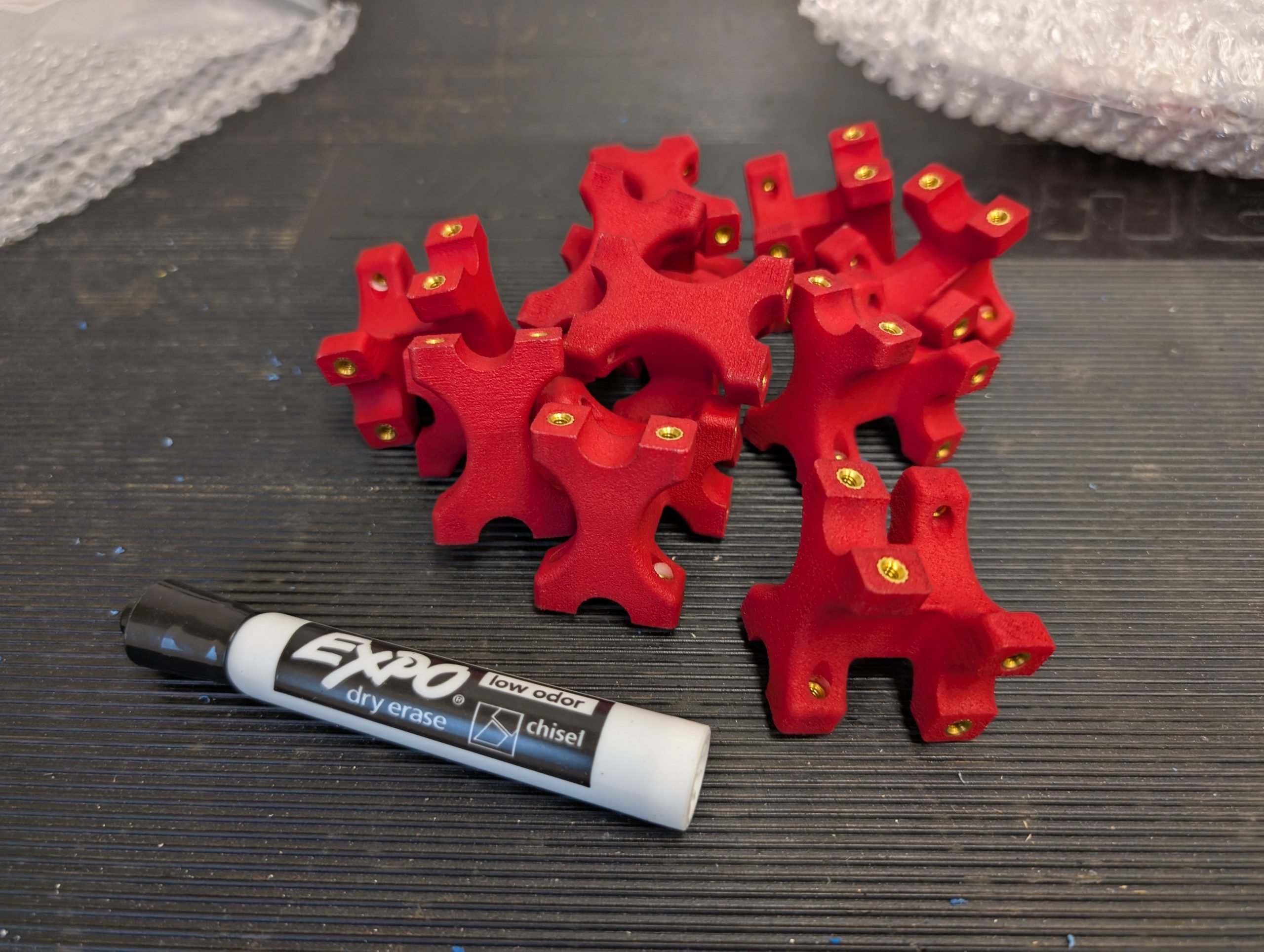
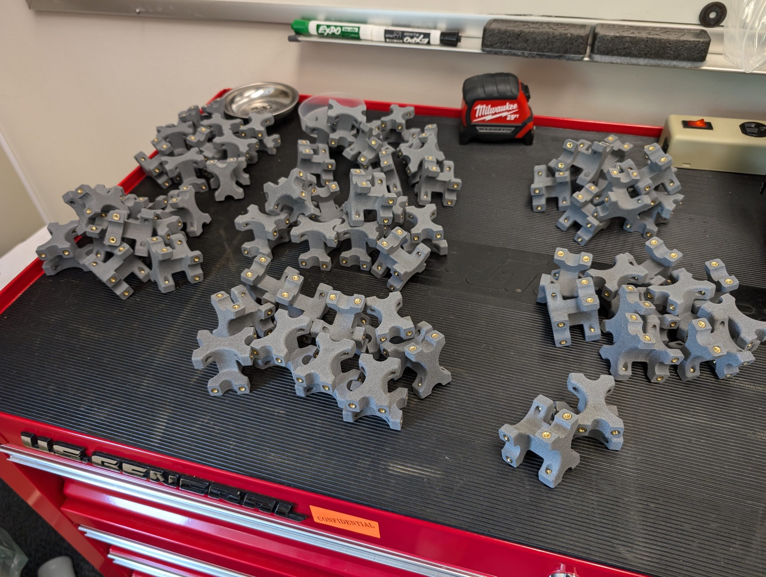
For the interface cabling between the power supplies and the stripline, the geometry the electrical team was demanding caused astronomical machining costs at the quantities we needed. They also wanted to use a UL 94 flame retardant material that was a challenge to find a machining vendor for. To get the cost down I designed the parts for Multi-Jet Fusion and Selective Laser Sintering 3D printing which lowered costs, allowed for fire-retardant material, and as a bonus we could get them in any color we wanted!