Currently radio frequency (RF) cavities in the Booster beamline at Fermilab use ferrite or garnet components to help tune the resonant frequency of the cavity. The permeability of these materials can be varied as a function of an applied magnetic bias field, which allows for tuning of the cavity without changing its physical geometry. Unfortunately, these garnet and ferrite materials are the primary contributor to RF power loss in the cavity. Physicists working on the Booster cavity obtained Laboratory Directed Research and Development (LDRD) funding to explore whether garnet manufactured using different heat treatments and material mixtures could create tuning devices with lower losses.
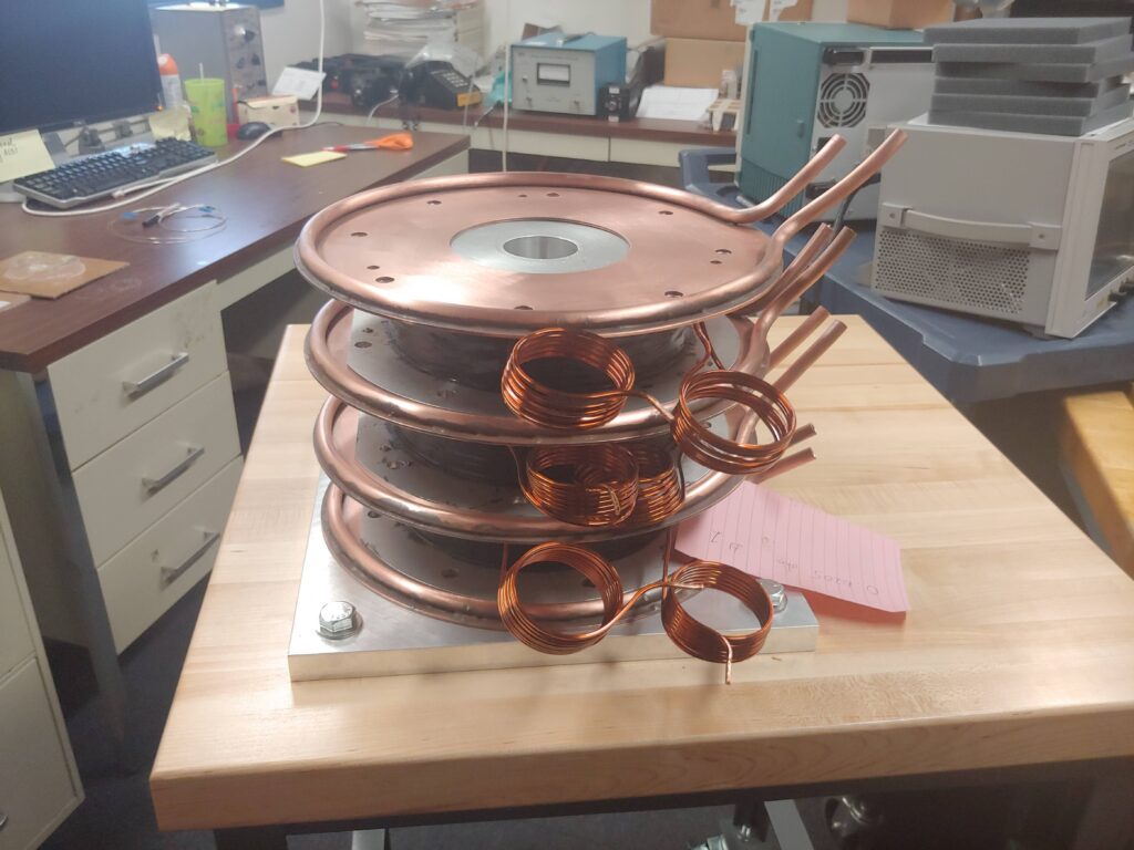
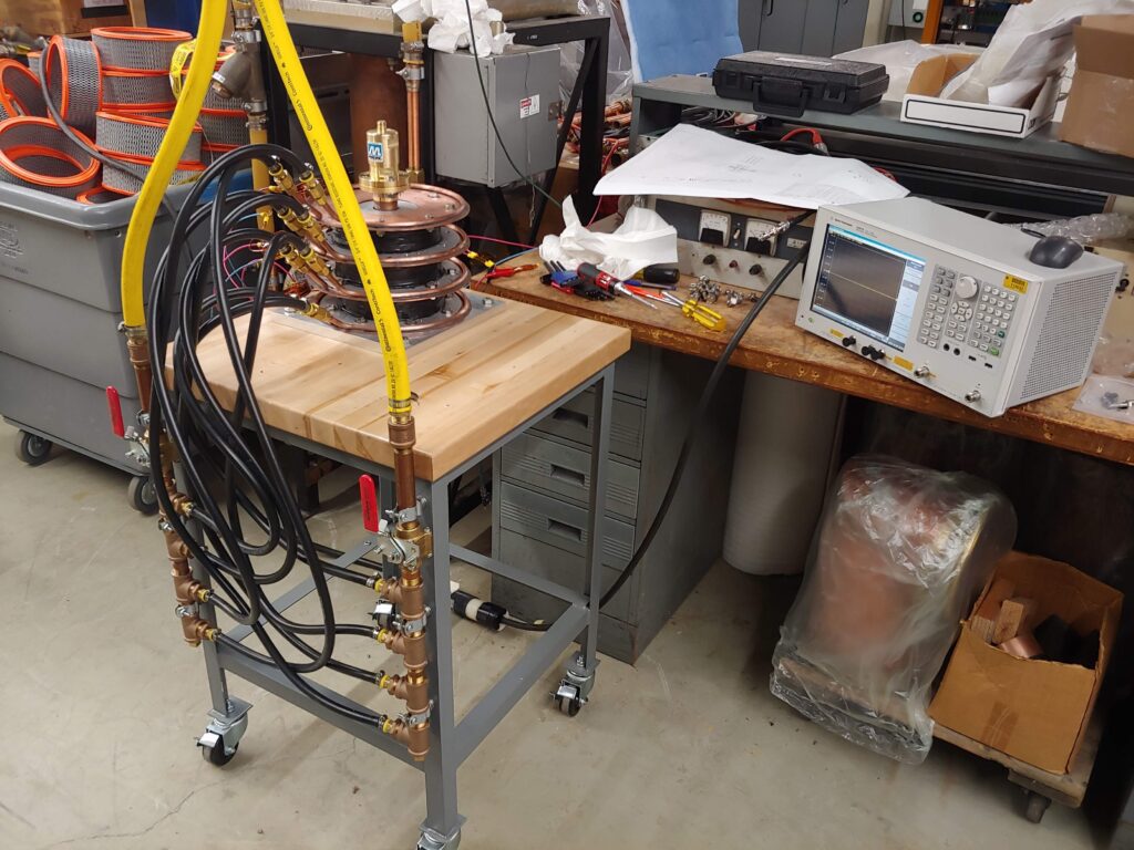
Collaborating with physicists, I designed a device that would allow for efficient testing of RF losses from a garnet specimen with an applied magnetic bias field. Anyone familiar with RF engineering may initially view this as a simple problem. To simplify it a bit, you just to place the specimen inside a coaxial RF tube, and then place that inside a solenoid to generate a bias field. The problem becomes significantly more difficult when you need to test 500 or more garnet samples.
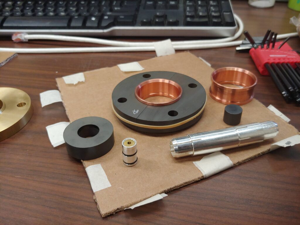
Creating a system that allows for installing and removing the sample quickly, while not measuring on the scope differently than a continuous RF conductor provided an interesting challenge. Physicists wanted all the conducting walls to be impossibly thin, while I wanted them to be thick enough to hold up to an absent-minded grad student loading in the 233rd specimen for the day. The final solution involved custom silver-plated beryllium copper bullets, several pieces of very precisely machined garnet, and three custom made aluminum spools with locating holes wrapped in square magnet wire. Copper cooling plates were also added to dissipate the heat generated by the solenoid during testing.
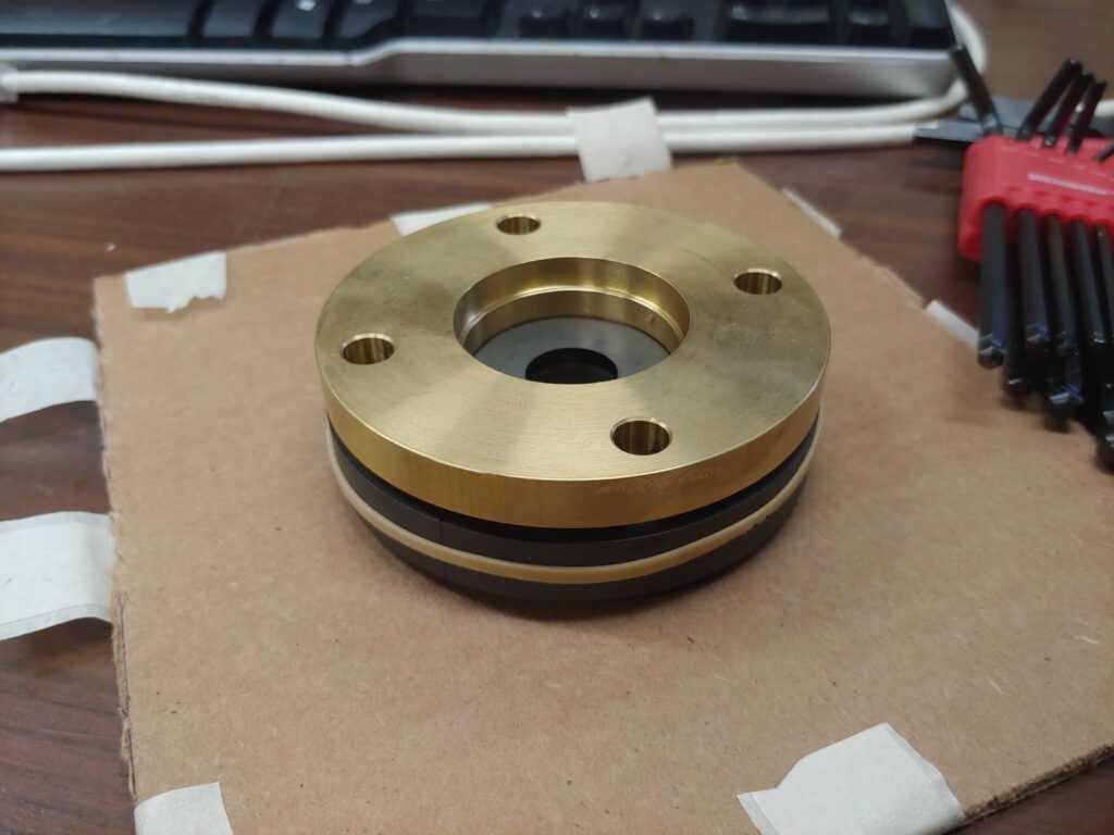
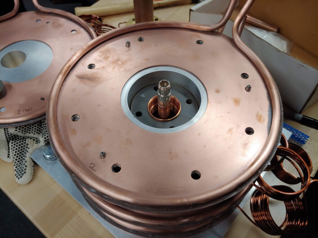
Making sure everything fit together well required extremely careful application of GD&T. To get as close to an ideal scenario as possible, all the parts had to fit with very tight clearances, and there was no time in the project schedule to allow parts to be re-made if they didn’t fit. Thanks to careful consideration on the drawings, all parts fit together exactly as intended.
Some have questioned my idea of buying a gorgeous maple top table and immediately drilling holes in it to mount the device, but having a dedicated workspace for an expensive project is almost always worth the cost. There’s nothing worse than having to compete for bench space when testing needs to be done, or having to haphazardly place an expensive experiment on a too-narrow-table!
